
Refit
- Make
- Rover
- Model
- 600 Rover 600 Repair Manual - Volumes 1 and 2 - 2nd Edition
- Section
- Repairs › Refit
Automatic gearboxRefit
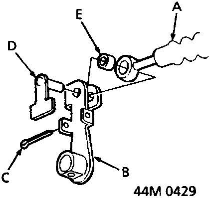
- Remove the split pin and lock pin, then separate the control lever from the selector cable. Discard split pin.
Refit
- Fit the selector cable in reverse order of removal.
- Use new exhaust pipe gaskets, self – locking nuts and split pin. Tighten exhaust pipe rear flange nuts to 55 Nm, front flange nuts to 34 Nm. Tighten cable guide bolts to 12 Nm.
- Check the selector cable adjustment after installing the cable.
- Fit front console, see BODY
SELECTOR CABLE
Adjust
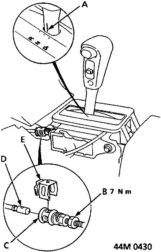
L.H.D. illustrated, R.H.D. is similar.
- Start the engine. Select reverse to see if the reverse gear engages. If not, refer to Hydraulic symptom to component chart.
- Switch off engine, remove the front console, see BODY
- Select N, then remove the lock pin from the cable adjuster.
Parts & tools for this job For Rover 600
- PARTTransmission filter kitSearch: Rover 600 transmission filter kit
- FLUIDAutomatic transmission fluidSearch: Rover automatic transmission fluid
- TOOLFluid transfer pumpSearch: fluid transfer pump
Links open Amazon search results in a new tab. As an Amazon Associate I earn from qualifying purchases.