
Components
- Make
- Rover
- Model
- 600 Rover 600 Repair Manual - Volumes 1 and 2 - 2nd Edition
- Section
- Repairs › Components
Automatic gearboxComponents · page 1 of 7
Components
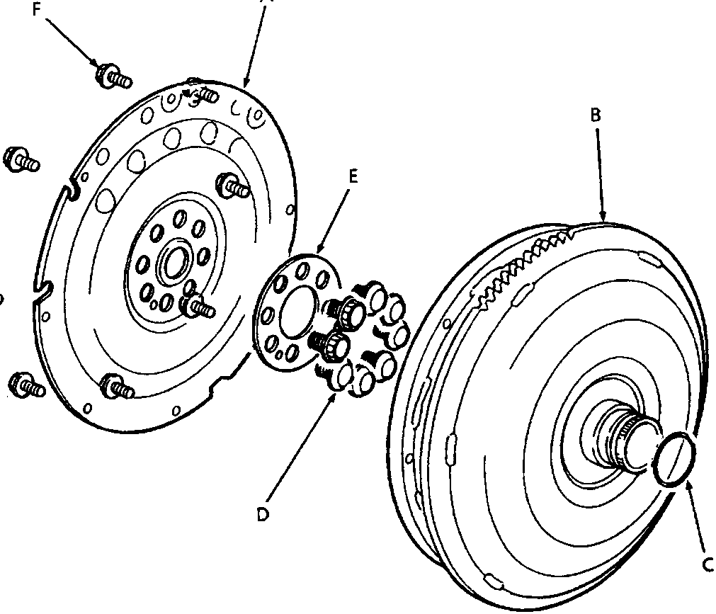
44M 0422
| A Drive plate | D Drive plate to crankshaft securing bolts |
| B Torque converter/ring gear | E Lock washer |
| C 'O' ring | F Drive plate to torque converter securing bolts |
Inspection/reassembling
- Check drive plate for cracks.
- Check ring gear for wear.
- Lubricate a new 'O' ring with transmission fluid and fit to torque converter output spigot.
- Tighten drive plate to crankshaft securing bolts by diagonal selection to 75 Nm.
CAUTION: Always fit a new lock washer.
- Tighten drive plate to torque converter securing bolts to 12 Nm.
Parts & tools for this job For Rover 600
- PARTTransmission filter kitSearch: Rover 600 transmission filter kit
- FLUIDAutomatic transmission fluidSearch: Rover automatic transmission fluid
- TOOLFluid transfer pumpSearch: fluid transfer pump
Links open Amazon search results in a new tab. As an Amazon Associate I earn from qualifying purchases.