
Components (page 2 of 7)
- Make
- Rover
- Model
- 600 Rover 600 Repair Manual - Volumes 1 and 2 - 2nd Edition
- Section
- Repairs
Automatic gearboxComponents · page 2 of 7
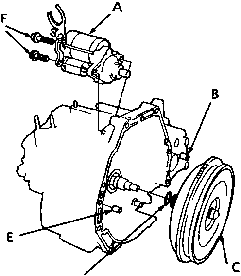
44M 0305
- A Starter motor
- B Dowel pin
- C Torque converter
- D 'O' ring
- E Dowel pin
- Install the starter motor on the torque converter housing, and install the 14 x 20 mm dowel pins and torque converter with a new O – ring in the torque converter housing.
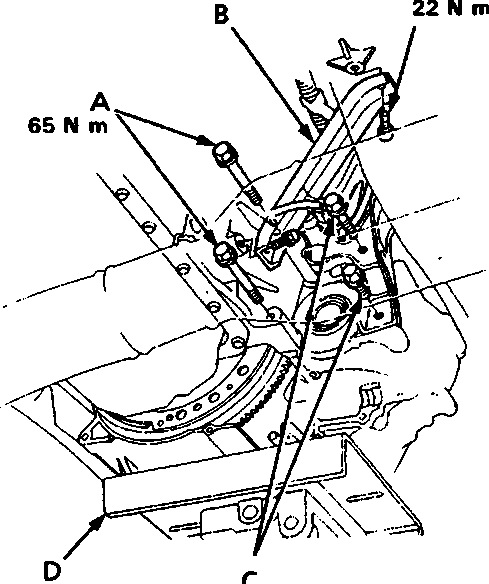
44M 0306
- A Gearbox housing mounting bolts.
- B Intake manifold bracket.
- C Rear engine mounting bolts.
- D Transmission jack
- Place the gearbox on the jack, raise to the engine assembly level.
- Attach the gearbox on the engine, then install the gearbox housing mounting bolts, rear engine mounting bolts and intake manifold bracket bolts.
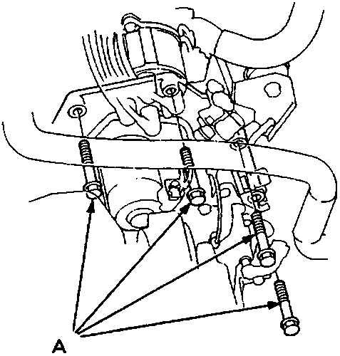
44M 0307
- A Gearbox housing mounting bolts.
- Install the gearbox housing mounting bolts.
Parts & tools for this job For Rover 600
- PARTTransmission filter kitSearch: Rover 600 transmission filter kit
- FLUIDAutomatic transmission fluidSearch: Rover automatic transmission fluid
- TOOLFluid transfer pumpSearch: fluid transfer pump
Links open Amazon search results in a new tab. As an Amazon Associate I earn from qualifying purchases.