
Oil Pump Drive/Driven Gear Thrust (Axial) Clearance:
- Make
- Rover
- Model
- 600 Rover 600 Repair Manual - Volumes 1 and 2 - 2nd Edition
- Section
- Repairs › Oil Pump Drive/Driven Gear Thrust (Axial) Clearance:
Automatic gearboxOil Pump Drive/Driven Gear Thrust (Axial) Clearance:
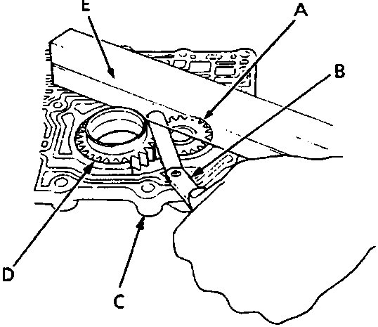
- Oil pump driven gear
- Feeler gauge
- Main valve body
- Oil pump drive gear
- Straight edge
- Remove the oil pump driven gear shaft. Measure the thrust clearance of the oil pump driven gear and oil pump drive gear – to – valve body.
Oil Pump Drive/Driven Gear Thrust (Axial) Clearance:
Standard (New) = 0.03 – 0.05 mm
Service Limit = 0.07 mm
Parts & tools for this job For Rover 600
- PARTOil filterSearch: Rover 600 oil filter
- TOOLOil filter wrenchSearch: oil filter wrench
- FLUIDEngine oilSearch: Rover 600 engine oil
Links open Amazon search results in a new tab. As an Amazon Associate I earn from qualifying purchases.