
Components
- Make
- Rover
- Model
- 600 Rover 600 Repair Manual - Volumes 1 and 2 - 2nd Edition
- Section
- Repairs › Components
Automatic gearboxComponents
Components
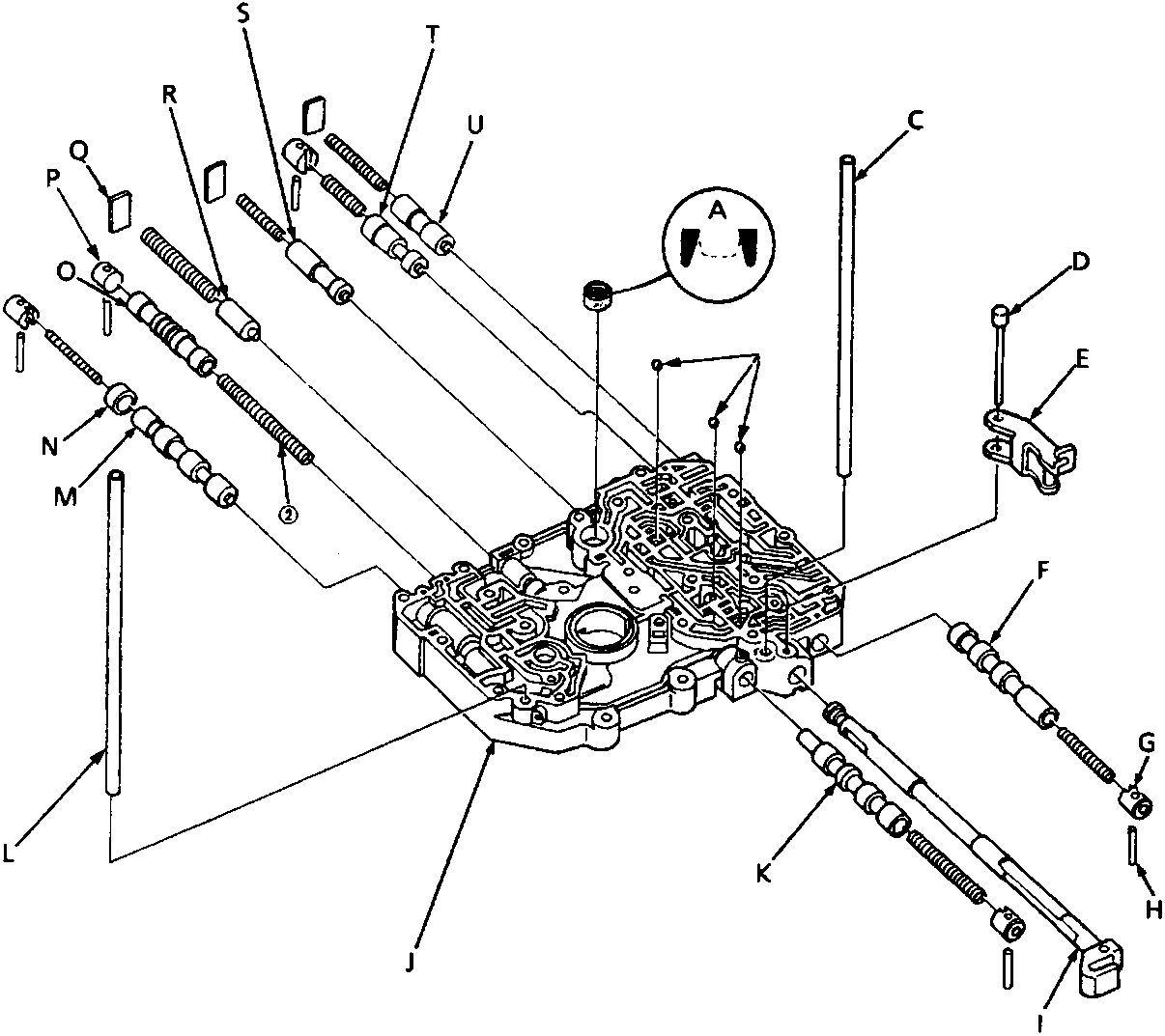
44M 0343
| A | Filter | L | Oil feed pipe |
| B | Check balls – 3 off | M | Lock – up control valve |
| C | Oil feed pipe | N | Sleeve |
| D | Detent arm shaft | O | Lock – up shift valve |
| E | Detent arm | P | Valve cap |
| F | 1 – 2 shift valve | Q | Valve spring seat |
| G | Valve spring cap | R | Cooler relief valve |
| H | Valve cap roller | S | Modulator valve |
| I | Manual valve | T | CPC valve |
| J | Main valve body | U | 3 – 2 kick – down valve |
| K | 2 – 3 shift valve |
Parts & tools for this job For Rover 600
- PARTTransmission filter kitSearch: Rover 600 transmission filter kit
- FLUIDAutomatic transmission fluidSearch: Rover automatic transmission fluid
- TOOLFluid transfer pumpSearch: fluid transfer pump
Links open Amazon search results in a new tab. As an Amazon Associate I earn from qualifying purchases.