
Dismantling
- Make
- Rover
- Model
- 600 Rover 600 Repair Manual - Volumes 1 and 2 - 2nd Edition
- Section
- Repairs › Dismantling
Automatic gearboxDismantling · page 1 of 2
Dismantling
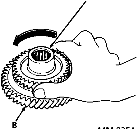
B Countershaft 2nd gear
- Separate countershaft 3rd gear from countershaft 1st gear by turning 3rd gear in the direction shown.
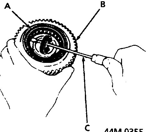
B Countershaft 1st gear
C Screwdriver
- Remove the one – way clutch by prising it up with the end of a screwdriver.
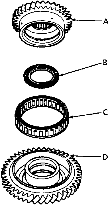
B Thrust needle bearing
C One way clutch
D 1st gear
- Inspect gears for wear, scoring and chipping of teeth.
- Check thrust needle bearing and one – way clutch for wear and smoothness of rotation.
- Replace components as necessary,
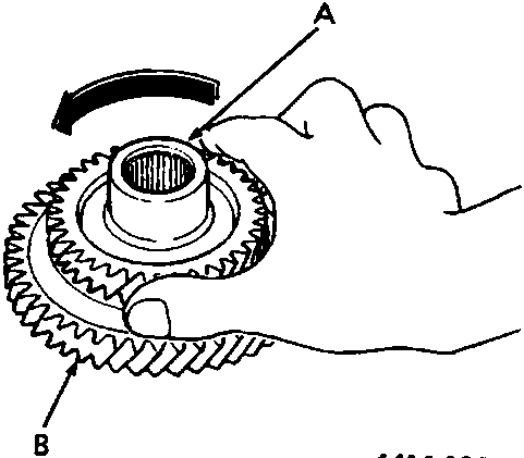
B Countershaft 1st gear
- After the parts are assembled, hold countershaft 1st gear and turn countershaft 3rd gear in the direction shown to ensure it turns freely.
Parts & tools for this job For Rover 600
- PARTTransmission filter kitSearch: Rover 600 transmission filter kit
- FLUIDAutomatic transmission fluidSearch: Rover automatic transmission fluid
- TOOLFluid transfer pumpSearch: fluid transfer pump
Links open Amazon search results in a new tab. As an Amazon Associate I earn from qualifying purchases.