
Abs2e hydraulic modulator ECU
- Make
- Rover
- Model
- Coupé, Cabriolet & Tourer 200/400 Coupé, Cabriolet & Tourer Workshop Manual
- Section
- Repairs › Abs2e hydraulic modulator ECU
BrakesAbs2e hydraulic modulator ECU
- Position sensor lead brackets to hub, lower arm and body. Fit and tighten bolts to 10 Nm.
- Check that 'O' ring is in place, reconnect sensor harness multiplug, ensure that both halves are correctly engaged.
- Secure multiplug to body clips.
- Fit road wheel and tighten nuts to 100 Nm.
- Remove stand(s) and lower vehicle.
- To ensure correct operation, the system MUST be tested using Microcheck.
ABS2E HYDRAULIC MODULATOR ECU
Service Repair No. 70.25.34
Remove
- Disconnect battery earth lead.
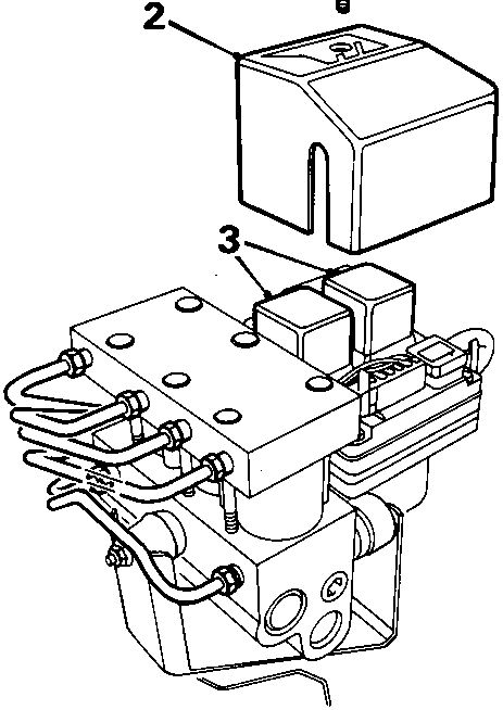
- Remove screw securing relay cover to ECU.
- Remove relay cover from ECU.
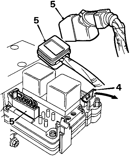
- Release metal clip from multiplug.
- Disconnect 3 multiplugs from ECU and position aside.
Note: Take care when disconnecting 15 pin connector from ECU as it is possible to break the bridge piece securing the connector to ECU.
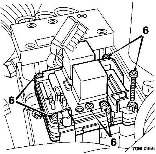
- Remove 6 TX20 Torx screws securing ECU to hydraulic modulator.
- Remove ECU from hydraulic modulator.
Do not carry out further dismantling if component is removed for access only
- Remove solenoid valve relay from ECU.
- Remove return pump relay from ECU.
- Fit relays to new ECU if necessary.
Parts & tools for this job For Rover Coupé, Cabriolet & Tourer
- PARTBrake padsSearch: Rover Coupé, Cabriolet & Tourer brake pads
- TOOLBrake bleeder kitSearch: one man brake bleeder kit
- FLUIDBrake fluidSearch: brake fluid
Links open Amazon search results in a new tab. As an Amazon Associate I earn from qualifying purchases.