
Refit
- Make
- Rover
- Model
- Coupé, Cabriolet & Tourer 200/400 Coupé, Cabriolet & Tourer Workshop Manual
- Section
- Repairs › Refit
BrakesRefit
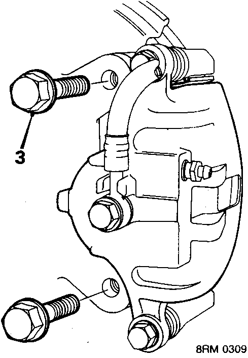
- Remove 2 bolts, front brake caliper to suspension hub.
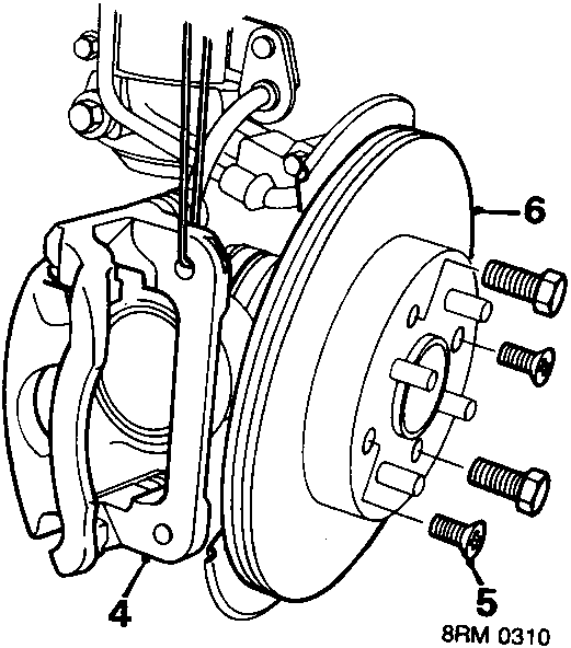
- Move caliper aside and tie clear of brake disc.
- Remove 2 screws securing brake disc to drive flange.
- Remove brake disc from drive flange, using jacking screws if necessary.
Refit
CAUTION: Excessive disc run – out can exist after fitting a new disc, with no immediate symptoms being evident during driving. The most likely cause of run – out is the presence of contaminants (e.g. rust or paint) or damage on mating faces of flange and disc, and disc and wheel. Excessive run – out will cause progressive uneven wear of the disc, leading to disc thickness variation, which is the cause of judder. Always ensure that the disc run – out checks given here are strictly adhered to.
- Inspect mating surfaces of new disc and drive flange and clean thoroughly using wire brush.
Note: There is no need to remove the silver protective coating from the friction surface of a new disc.
- Fit brake disc to drive flange and secure using 4 x M12 nuts (not the wheel nuts). Tighten nuts to 70 Nm.
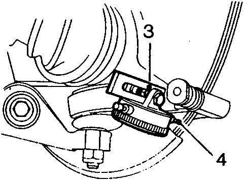
- Mount a dial test indicator to caliper lower mounting hole using tool 18G 191-9.
- Position dial test indicator probe 6 mm from disc outer edge.
- Rotate disc at least one complete turn and measure disc run – out.
Front disc run – out limit with wheel off = 0.050 mm.
Run – out exceeds limit
- Mark disc to drive flange relationship, remove 4 x M12 nuts retaining disc and remove disc from drive flange. Check mating surfaces again for contaminants then refit disc 180° from previous position and secure with nuts. Recheck run – out.
- If run – out is still excessive, skim brake discs using an on car disc lathe.
- If a lathe is not available, fit new drive flange and/or bearings and recheck run – out.
Run – out within limit
- Remove dial test indicator and tool 18G 191-9. Remove 4 x M12 nuts and secure disc with the new screws tightened to 6 Nm.
- Wipe pads and shims clean.
- Fit shims to pads.
- Position brake pads and locate caliper assembly to disc.
- Secure caliper using top mounting bolt only.
- Inspect wheel and disc mating surfaces and remove any contaminants.
- Fit road wheel and tighten nuts to 100 Nm.
Parts & tools for this job For Rover Coupé, Cabriolet & Tourer
- PARTBrake padsSearch: Rover Coupé, Cabriolet & Tourer brake pads
- TOOLBrake bleeder kitSearch: one man brake bleeder kit
- FLUIDBrake fluidSearch: brake fluid
Links open Amazon search results in a new tab. As an Amazon Associate I earn from qualifying purchases.