
Refit
- Make
- Rover
- Model
- Coupé, Cabriolet & Tourer 200/400 Coupé, Cabriolet & Tourer Workshop Manual
- Section
- Repairs › Refit
BrakesRefit
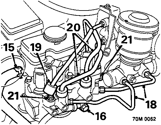
- Release clip securing pump feed hose to reservoir and disconnect hose.
CAUTION: Plug the connections.
- Remove banjo bolt securing pump return hose to modulator.
CAUTION: Plug the connections.
- Position an absorbant cloth below master cylinder to collect any fluid spillage.
CAUTION: Do not allow brake fluid to contact paint finished surfaces as paint may be damaged. If spilled, remove fluid and clean area with clean warm water.
- Slacken unions securing primary and secondary circuit brake pipes to the master cylinder and modulator, remove brake pipes.
CAUTION: Plug the connections.
- Lift brake pipe protective sleeves to gain access to unions.
- Slacken unions securing rear brake pipes to modulator and rear pipe adaptor, remove brake pipes.
CAUTION: Plug the connections.
- Slacken unions and disconnect front brake pipes from modulator.
CAUTION: Plug the connections.
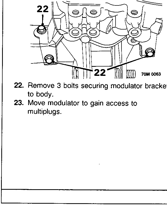
- Remove 3 bolts securing modulator bracket to body.
- Move modulator to gain access to multiplugs.
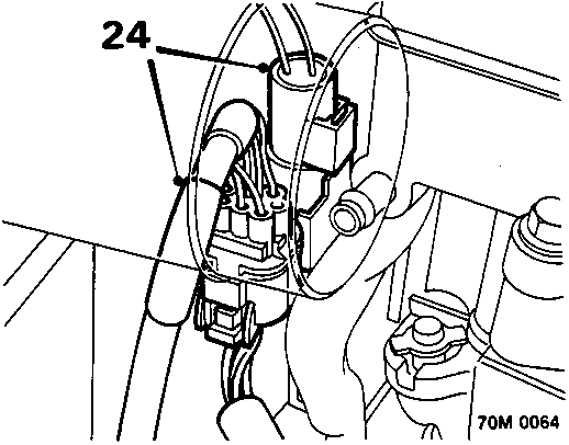
- Disconnect 2 harness multiplugs.
- Release multiplugs from modulator bracket.
- Remove modulator assembly
Do not carry out further dismantling if component is removed for access only
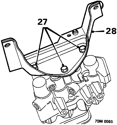
- Remove 3 bolts securing bracket to modulator.
- Remove bracket.
Refit
- Fit modulator mounting bracket to modulator. Fit and tighten 3 bolts.
- Position modulator assembly to vehicle, secure multiplugs to modulator bracket.
- Connect harness multiplugs to modulator.
- Align modulator bracket to body, fit 3 bolts and tighten to 22 Nm.
- Remove plugs from brake pipes, modulator ports, rear brake pipe adaptor and master cylinder.
- Connect front brake pipes to modulator, tighten pipe unions to 18 Nm.
- Connect rear brake pipes to modulator and rear pipe adaptor, tighten pipe unions to 18 Nm.
- Connect primary and secondary circuit pipes between master cylinder and modulator, tighten unions to 20 Nm.
- Remove plugs from pump feed hose and reservoir, connect hose to reservoir and secure with clip.
Parts & tools for this job For Rover Coupé, Cabriolet & Tourer
- PARTBrake padsSearch: Rover Coupé, Cabriolet & Tourer brake pads
- TOOLBrake bleeder kitSearch: one man brake bleeder kit
- FLUIDBrake fluidSearch: brake fluid
Links open Amazon search results in a new tab. As an Amazon Associate I earn from qualifying purchases.