
Refit
- Make
- Rover
- Model
- Coupé, Cabriolet & Tourer 200/400 Coupé, Cabriolet & Tourer Workshop Manual
- Section
- Repairs › Refit
BrakesRefit
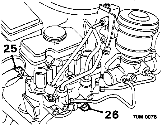
- Release clip securing pump feed hose to reservoir and disconnect hose.
CAUTION: Plug the connections.
- Remove banjo bolt securing pump return hose to modulator.
CAUTION: Plug the connections.
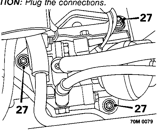
- Remove 3 nuts securing pump assembly to mounting plate
- Release and remove pump assembly.
Refit
- Fit pump assembly to mounting plate, tighten nuts to 10 Nm.
- Remove plugs from pump feed hose and reservoir, connect hose to reservoir and secure with clip.
- Remove plugs from from pump return hose and modulator, secure hose to modulator with banjo bolt, tighten to 35 Nm.
- Remove absorbant cloth.
- Connect lead to pressure switch and secure to bracket.
- Connect pump motor multiplug to harness and secure to bracket.
- Align pump relay box to bonnet lock platform, fit and tighten bolt to 9 Nm.
- Position intake duct to bonnet platform, fit and tighten nuts to 9 Nm.
- Secure air cleaner elbow to intake air duct.
- Secure intake air duct side branch to fan cowi.
- Secure expansion tank hose to clips on intake air duct.
- Position battery tray support bracket to inner wing and tighten bolts to 9 Nm.
- Position battery tray, fit and tighten bolts to 9 Nm.
- Align pump feed hose clip and throttle cable bracket to battery tray, fit and tighten bolts to 9 Nm.
- Position pump feed hose bracket to battery tray, fit bolt and tighten to 9 Nm.
- Fit battery.
- Bleed ABS6 high pressure system, see Adjustments
- To ensure correct operation, the system MUST be tested using Microcheck.
ABS6 PRESSURE SWITCH
Service Repair No. 70.25.44
Remove
- Remove pump assembly, see ABS6 pump assembly.
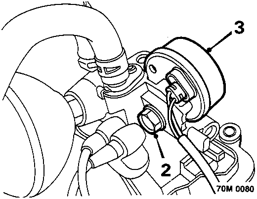
- Slacken bolt securing pressure switch to pump assembly.
- Release and remove pressure switch.
Refit
- Fit pressure switch to pump assembly.
- Align pressure switch to pump assembly
- Tighten bolt securing pressure switch to pump assembly.
- Fit pump assembly, see ABS6 pump assembly.
- To ensure correct operation, the system MUST be tested using Microcheck.
Parts & tools for this job For Rover Coupé, Cabriolet & Tourer
- PARTBrake padsSearch: Rover Coupé, Cabriolet & Tourer brake pads
- TOOLBrake bleeder kitSearch: one man brake bleeder kit
- FLUIDBrake fluidSearch: brake fluid
Links open Amazon search results in a new tab. As an Amazon Associate I earn from qualifying purchases.