
Refit (page 2 of 2)
- Make
- Rover
- Model
- Coupé, Cabriolet & Tourer 200/400 Coupé, Cabriolet & Tourer Workshop Manual
- Section
- Repairs
BrakesRefit · page 2 of 2
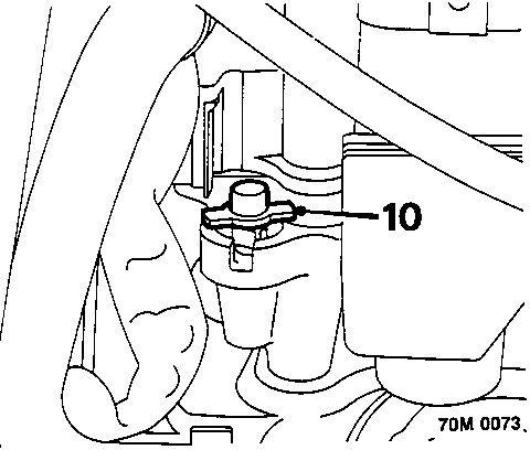
- Clean area around modulator bleed screw and remove protective cap.
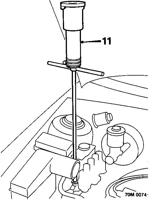
- Fit 'T' wrench of tool SMD 4081 to bleed screw. Ensure filler cap is fitted to 'T' wrench reservoir.
- Slowly open bleed screw using 'T' wrench, allow brake fluid to enter 'T' wrench reservoir. Close bleed screw when fluid stops rising or when reservoir is full.
- If reservoir becomes full, dispose of fluid and repeat operation until all pressure is released.
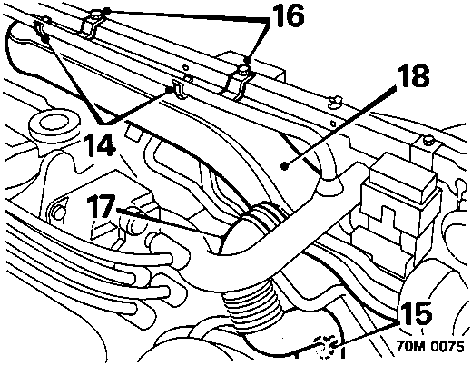
- Release 2 clips securing expansion tank hose to intake air duct.
- Release clip securing intake air duct side branch to fan cowl.
- Remove 2 bolts, intake air duct to bonnet lock platform.
- Release intake air duct from air cleaner elbow
- Remove intake air duct.
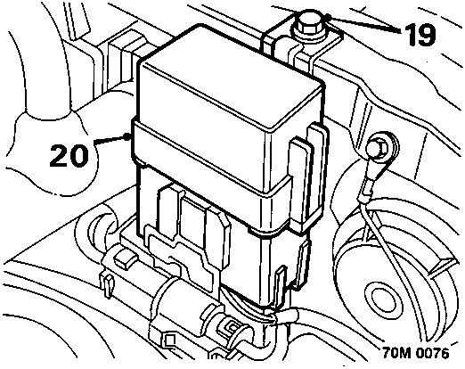
- Remove bolt securing pump relay box to bonnet lock platform.
- Position pump relay box aside.
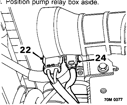
- Release pump motor multiplug from bracket.
- Disconnect pump motor multiplug from harness.
- Release pressure switch lead from bracket
- Disconnect pressure switch connector.
Parts & tools for this job For Rover Coupé, Cabriolet & Tourer
- PARTBrake padsSearch: Rover Coupé, Cabriolet & Tourer brake pads
- TOOLBrake bleeder kitSearch: one man brake bleeder kit
- FLUIDBrake fluidSearch: brake fluid
Links open Amazon search results in a new tab. As an Amazon Associate I earn from qualifying purchases.