
Abs6 front wheel sensor and harness
- Make
- Rover
- Model
- Coupé, Cabriolet & Tourer 200/400 Coupé, Cabriolet & Tourer Workshop Manual
- Section
- Repairs › Abs6 front wheel sensor and harness
BrakesAbs6 front wheel sensor and harness
ABS6 FRONT WHEEL SENSOR AND HARNESS
Service Repair No. 70.25.32
Remove
- Raise front of vehicle.
WARNING: Support on safety stands.
- Remove road wheel(s).
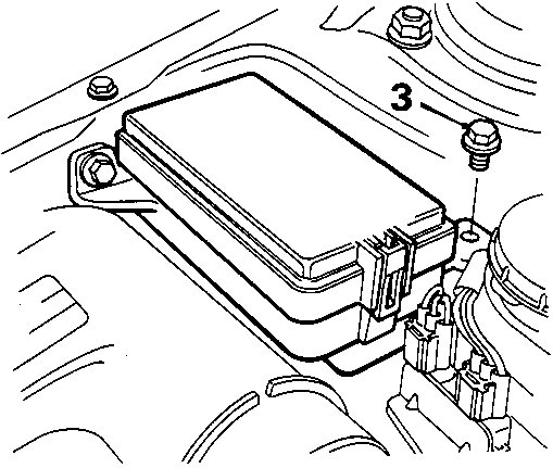
- Remove bolts retaining under – bonnet fusebox.
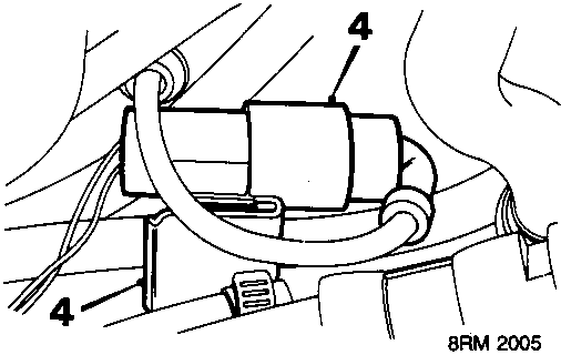
- Release sensor harness multiplug from under – bonnet bracket and disconnect multiplug.
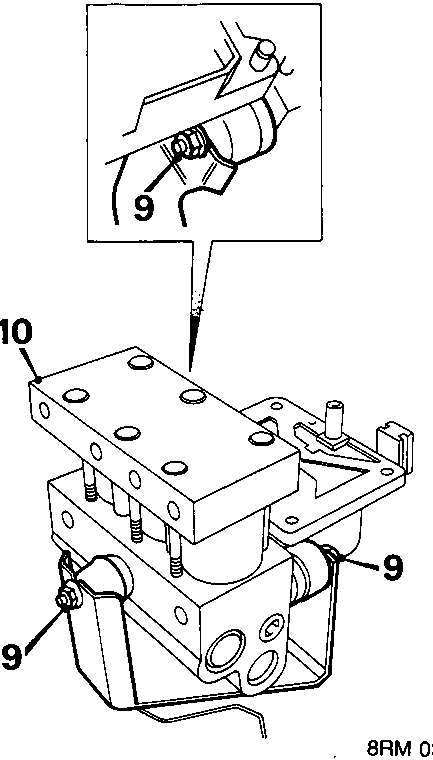
- Slacken 3 mounting nuts from modulator.
- Remove hydraulic modulator from vehicle.
Do not carry out further dismantling if component is removed for access only
- Remove 3 mounting rubbers from modulator.
- Fit mounting rubbers to new modulator.
Refit
- Position and align hydraulic modulator to mounting bracket.
- Tighten 3 mounting nuts to 10 Nm.
- Remove plugs from the ends of the brake pipes and from the modulator ports.
- Connect brake pipe unions to modulator unit. Ensure that the pipes are connected to their corresponding port on the modulator.
Note: The pipes are identified by labels on the pipes and the ports by stampings on the modulator.
RF = R.H.F., LF = L.H.F., RR = R.H.R., LR = L.H.R.
- Tighten brake pipe unions to 22 Nm.
- Remove absorbent cloth from blow modulator brake unions.
- Connect earth lead to modulator, fit and tighten nut.
- Fit ECU to hydraulic modulator, see ABS2E hydraulic modulator ECU.
- Connect battery earth lead.
- To ensure correct operation, the system MUST be tested using Microcheck.
Parts & tools for this job For Rover Coupé, Cabriolet & Tourer
- TOOLOBD2 scannerSearch: OBD2 scanner
- TOOLDigital multimeterSearch: automotive digital multimeter
- TOOLBack-probe test leadsSearch: back probe test leads
Links open Amazon search results in a new tab. As an Amazon Associate I earn from qualifying purchases.