
Remove
- Make
- Rover
- Model
- Coupé, Cabriolet & Tourer 200/400 Coupé, Cabriolet & Tourer Workshop Manual
- Section
- Repairs › Remove
BrakesRemove
Service Repair No. Non - Return Valve – 70.50.15
Remove
ABS2E models
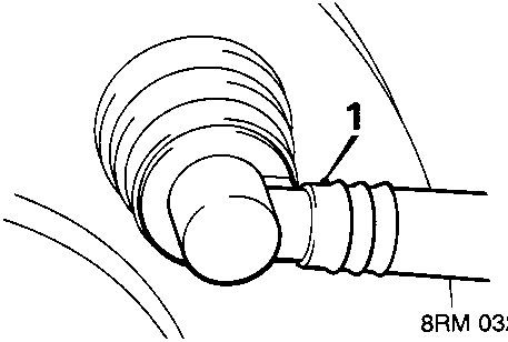
- Release servo non return valve from grommet in servo.
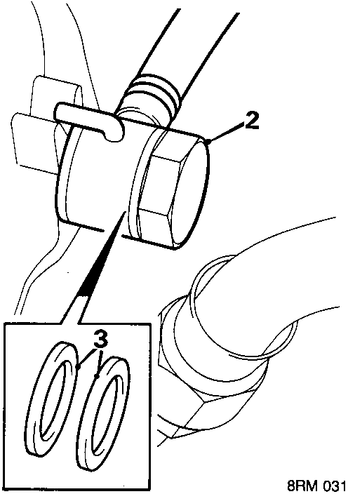
- Remove banjo bolt securing servo hose from inlet manifold.
- Discard banjo bolt sealing washers.
Note: ABS2E models the non – return valve and hoses are renewed as an assembly.
ABS6 models
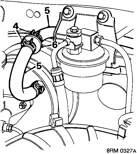
- Release 2 clips securing hoses to non – return valve.
- Release hoses from non – return valve.
- Remove non – return valve.
Refit
ABS2E models
- Clean banjo bolt and fit new sealing washers.
- Fit servo hose to inlet manifold with banjo bolt and tighten to 50 Nm.
- Secure non – return valve into the grommet on the servo.
ABS6 models
- Fit servo hoses to non – return valve and secure with clips
Note: Ensure that the arrow on the non – return valve points towards the manifold.

Parts & tools for this job For Rover Coupé, Cabriolet & Tourer
- PARTBrake padsSearch: Rover Coupé, Cabriolet & Tourer brake pads
- TOOLBrake bleeder kitSearch: one man brake bleeder kit
- FLUIDBrake fluidSearch: brake fluid
Links open Amazon search results in a new tab. As an Amazon Associate I earn from qualifying purchases.