
Handbrake lever and switch
- Make
- Rover
- Model
- Coupé, Cabriolet & Tourer 200/400 Coupé, Cabriolet & Tourer Workshop Manual
- Section
- Repairs › Handbrake lever and switch
BrakesHandbrake lever and switch
HANDBRAKE LEVER AND SWITCH
Service Repair No. Lever – 70.35.08
Service Repair No. Switch – 70.35.40
Remove
- Remove rear console if fitted, see BODY – Repairs.
- Remove high centre console if fitted, see BODY – Repairs.
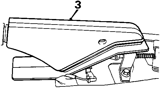
8RM 0314A
- Remove rubber gaiter from handbrake lever.
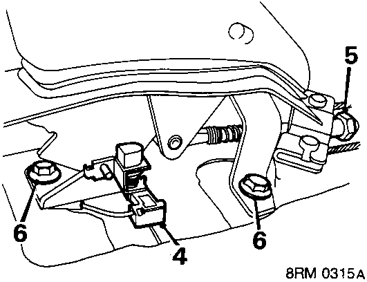
8RM 0315A
- Disconnect Lucar connector from brake warning switch.
- Slacken cable adjustment nut.
- Remove bolts securing handbrake assembly to floor. Lift handbrake assembly clear.
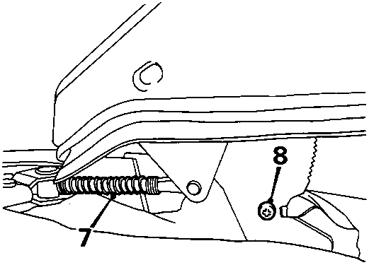
8RM 0316A
- Remove spring from adjusting rod.
- Remove screw, warning switch to handbrake quadrant.
- Remove warning switch.
Refit
- Screw warning switch to handbrake quadrant.
- Fit spring to adjusting rod.
- Bolt handbrake lever assembly to floor.
- Start cable adjustment nut.
- Connect Lucar connector to brake warning switch.
- Fit rubber gaiter to handbrake lever.
- Adjust handbrake cable, see MAINTENANCE
- Fit high centre console if fitted, see BODY – Repairs.
- Fit rear console if fitted, see BODY – Repairs.
HANDBRAKE CABLE
Service Repair No. 70.35.16
Remove
- Raise rear of vehicle.
WARNING: Support on safety stands.
- Remove road wheel(s).
- If fitted, remove high centre console, see BODY – Repairs.
- If fitted, remove rear console, see BODY – Repairs.
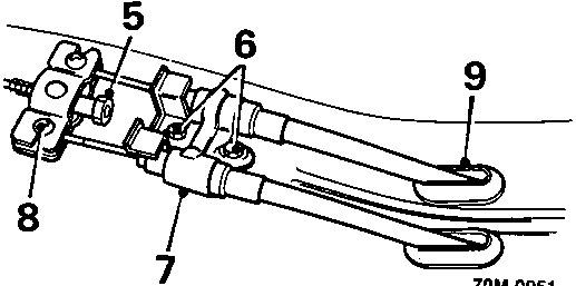
70M 0031
- Remove handbrake cable adjusting nut.
- Remove 2 bolts, cable retaining plate to tunnel.
- Remove cable retaining plate.
- Release cable from compensating plate.
- Release cable grommet from tunnel.
- Remove exhaust centre heat shield see MANIFOLD & EXHAUST – Repairs
Parts & tools for this job For Rover Coupé, Cabriolet & Tourer
- TOOLOBD2 scannerSearch: OBD2 scanner
- TOOLDigital multimeterSearch: automotive digital multimeter
- TOOLBack-probe test leadsSearch: back probe test leads
Links open Amazon search results in a new tab. As an Amazon Associate I earn from qualifying purchases.