
Refit
- Make
- Rover
- Model
- Coupé, Cabriolet & Tourer 200/400 Coupé, Cabriolet & Tourer Workshop Manual
- Section
- Repairs › Refit
BrakesRefit · page 1 of 2
- If reservoir becomes full, dispose of fluid and repeat operation until all pressure is released.
- Position absorbant cloth to collect any fluid spillage.
CAUTION: Do not allow brake fluid to contact paint finished surfaces as paint may be damaged. If spilled, remove fluid and clean area with clean warm water.
- Using a spanner, slacken accumulator from pump assembly.
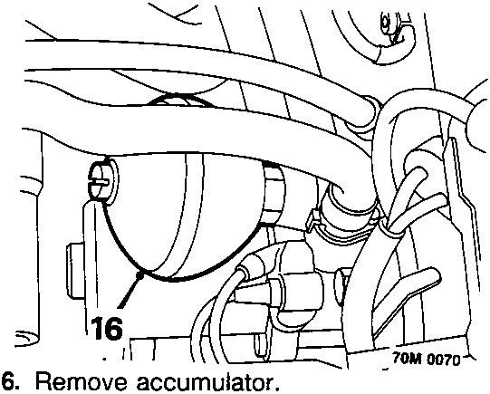
16. Remove accumulator.
- Remove and discard accumulator 'O' ring.
WARNING: The accumulator contains nitrogen gas under pressure. A risk of explosion exists if the container is punctured, exposed to high temperature or improperly dismantled. Before disposing of an accumulator, proceed as follows:
- Mount accumulator firmly in a bench vice, ensuring that the relief screw is uppermost.
- Slowly turn the screw three and one – half turns. Wait 3 minutes for all pressure to escape.
- Remove screw completely. Accumulator can then be disposed off.
Refit
- Clean mating faces of accumulator and pump assembly.
- Lubricate and fit new 'O' ring to accumulator.
- Fit and tighten accumulator to pump assembly .
- Remove absorbant cloth.
- Position battery tray support bracket to inner wing and tighten bolts to 9 Nm.
- Position battery tray, fit and tighten bolts to 9 Nm.
- Align pump feed hose clip and throttle cable bracket to battery tray, fit and tighten bolt to 9 Nm.
- Fit battery.
- Bleed ABS6 high pressure system, see Adjustments.
- To ensure correct operation, the system MUST be tested using Microcheck.
ABS6 PUMP ASSEMBLY
Service Repair No. 70.25.41
Remove
- Remove battery.
- Position absorbant cloth to collect any fluid spillage.
CAUTION: Do not allow brake fluid to contact paint finished surfaces as paint may be damaged. If spilled, remove fluid and clean area with clean warm water.
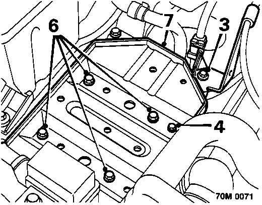
- Remove bolt securing pump feed hose clip and throttle cable bracket to battery tray.
- Remove bolt securing pump feed hose bracket to battery tray.
- Position pump feed hose aside.
- Remove 4 bolts securing battery tray to support bracket.
- Remove battery tray.
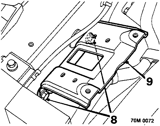
- Slackening 2 bolts securing battery tray support bracket to inner wing.
- Remove battery tray support bracket.
Parts & tools for this job For Rover Coupé, Cabriolet & Tourer
- PARTBrake padsSearch: Rover Coupé, Cabriolet & Tourer brake pads
- TOOLBrake bleeder kitSearch: one man brake bleeder kit
- FLUIDBrake fluidSearch: brake fluid
Links open Amazon search results in a new tab. As an Amazon Associate I earn from qualifying purchases.