
Alfa romeo code
- Make
- Alfa Romeo
- Model
- 145/146 Electrical System Diagnosis Manual, Volume 3
- Year
- 1994–2001
- Section
- Electrical components › Alfa romeo code
145 electrical system diagnosisAlfa romeo code
ALFA ROMEO CODE
NOTE: For the detailed description and operation of the Alfa Romeo Code see "Group 55 - ELECTRIC SYSTEM DIAGNOSIS".
REMOVING/REFITTING THE CONTROL UNIT
- Disconnect the battery (-) terminal.
- Remove the fusebox trim (see GROUPO 70).
- Slacken the two fastening bolts, withdraw the Alfa Romeo Code control unit, then remove it after disconnecting the two electrical connections.
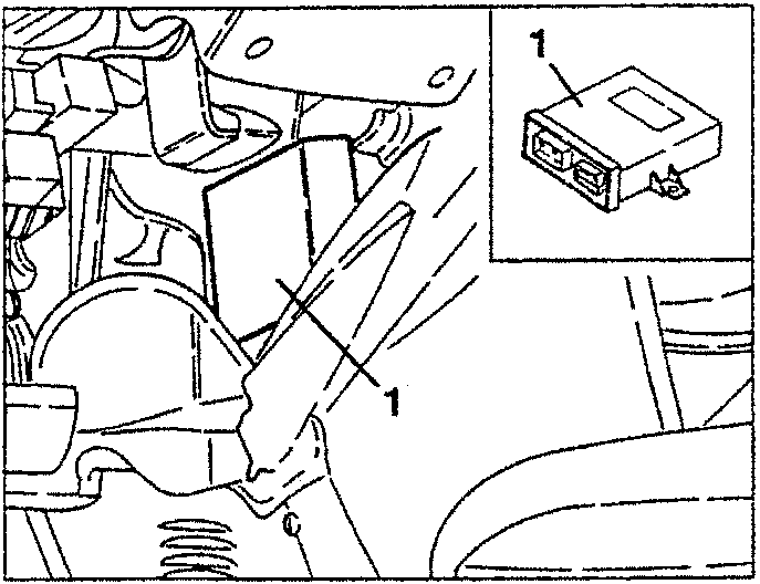
- Remove the Alfa Romeo Code control unit (see specific paragraph).
- Remove the Alfa Romeo Code antenna complete with the wiring connecting to the control unit.
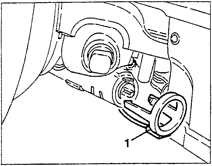
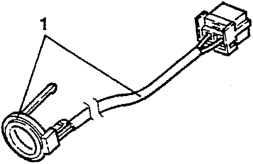
REMOVING/REFITTING THE ANTENNA
- Disconnect the battery (-) terminal.
- Slacken the four fastening screws and remove the lower steering column half box.
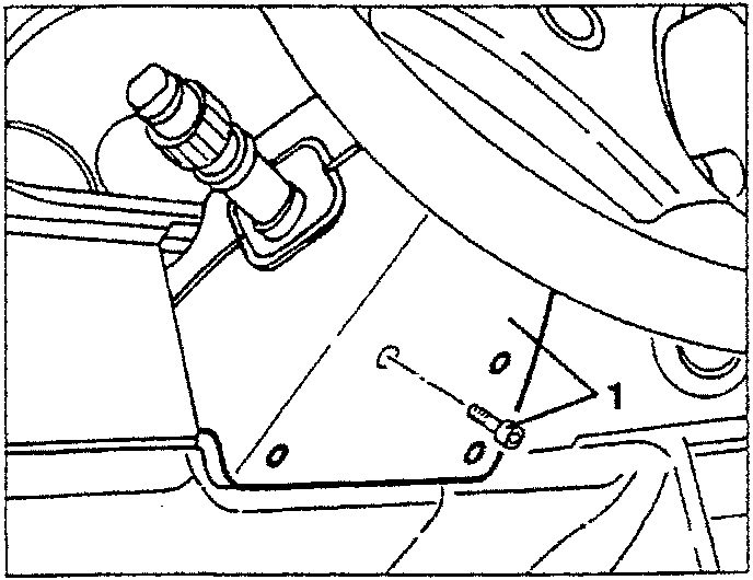
- Remove the fusebox cover (see GROUPO 70).
- Release the fastening clips and withdraw the Alfa Romeo Code antenna from the steering block.
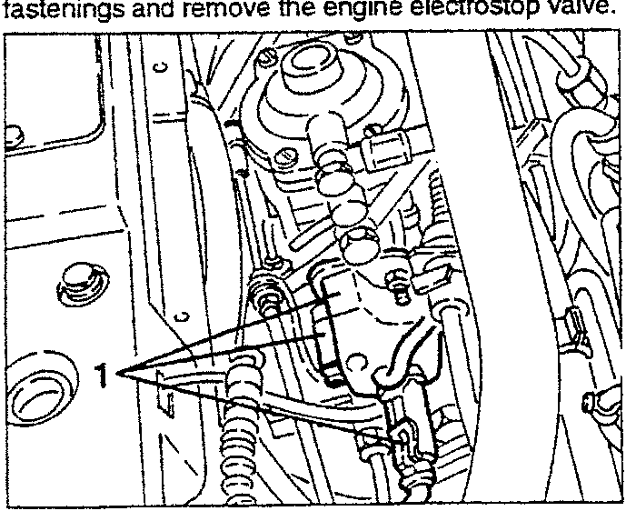
REMOVING/REFITTING THE ENGINE ELECTROSTOP VALVE (Specific for Turbodiesel engine)
- Disconnect the battery (-) terminal.
- Disconnect the electrical connection, slacken the fastenings and remove the engine electrostop valve.
Parts & tools for this job For 1994 Alfa Romeo 145/146
- TOOLDigital multimeterSearch: automotive digital multimeter
- PARTAssorted fuse kitSearch: car fuse assortment kit
- TOOLWire crimper and connector kitSearch: wire crimper connector kit
Links open Amazon search results in a new tab. As an Amazon Associate I earn from qualifying purchases.