
Dis-assembly
- Make
- Alfa Romeo
- Model
- 145/146 Electrical System Diagnosis Manual, Volume 3
- Year
- 1994–2001
- Section
- Electrical components › Dis-assembly
145 electrical system diagnosisDis-assembly · page 1 of 3
DIS-ASSEMBLY
- Bush
- Support on drive side
- Coupling relay rotor
- Return spring
- Coupling relay
- Starting coupling
- Fork levers
- Rubber pad
- Differential control gear
- Inverter
- Protection plate
- Pole frame
- Rotor
- Brush holder plate
- Felt ring
- Collector side support
- Bush
- Compensation washer
- Dust guard
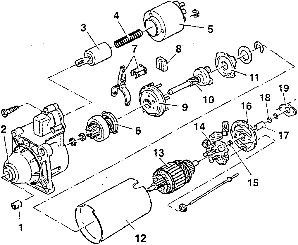
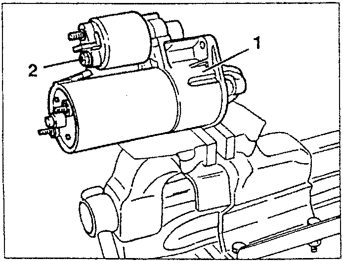
CAUTION: Because of their structure these starter motors are more sensitive to knocks, blows and squashing than the previous versions. Consequently, they must be fastened only locking them in the clamp on the flange (not on the pole frame).
- Fasten the starter motor on a vice with protective clamps as shown in the figure.
- Slacken the nut fastening the terminal to the coupling relay.
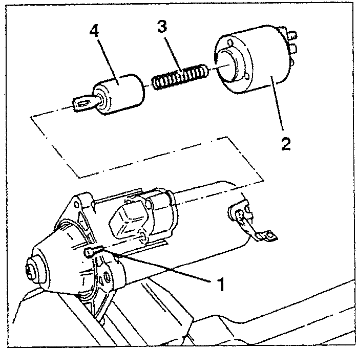
- Slacken the three screws fastening the coupling relay to the drive side support.
- Remove the coupling relay.
- Retrieve the return spring.
- Remove the coupling relay rotor.
Parts & tools for this job For 1994 Alfa Romeo 145/146
- TOOLDigital multimeterSearch: automotive digital multimeter
- PARTAssorted fuse kitSearch: car fuse assortment kit
- TOOLWire crimper and connector kitSearch: wire crimper connector kit
Links open Amazon search results in a new tab. As an Amazon Associate I earn from qualifying purchases.