
Rotor insulation test
- Make
- Alfa Romeo
- Model
- 145/146 Electrical System Diagnosis Manual, Volume 3
- Year
- 1994–2001
- Section
- Electrical components › Rotor insulation test
145 electrical system diagnosisRotor insulation test
Rotor insulation test
- Place one tester prod on a collector ring and the other on the rotor core and check that the tester does not indicate the passage of current.
- Repeat the operation for the second collector ring.
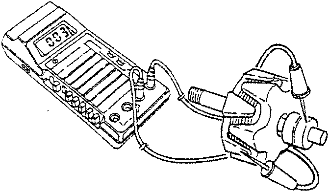
Measuring concentricity of the rotor and collector rings
- Position the rotor on special supports and using a dial gauge on a magnetic base check that the eccentricity of the rotor outside diameter does not exceed 0.05 mm.
- In the same way, check that the movement on the collector rings does not exceed 0.03 mm. Otherwise, turn the outside of the collector rings.
Stator winding insulation test
- Place one tester prod on the stator pack and the other on the terminal of the first phase, then on that of the second and third phase and check that the tester does not indicate the passage of current. If insulation is lacking, change the stator.
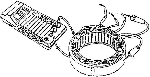
Stator winding continuity test
- Connect the tester terminals respectively on the terminals of phases 1-2, 1-3 and 2-3 and check that the tester indicates the passage of current in all three phases.
In the lack of continuity, change the stator.
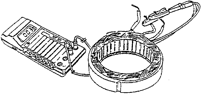
Checking the anti-disturbance condenser
- Connect the tester prods to the electrical connection and to the fastening plate of the condenser and check that the electrical capacity is within the specified rate.
| F4 Anti-disturbance condenser electrical capacity |
|---|
| 2.2 µF |
- In the lack of the specified rates, change the anti-disturbance condenser.
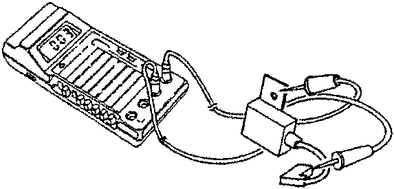
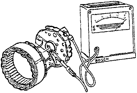
Checking the rectifier
- Check the operation of the cabled rectifier using suitable equipment.
- Connect the terminals of the test equipment to the following measurement points:
- a) Winding frame and terminals
- b) B+ and winding terminals
- c) D+ and winding terminals
The rectifier is in order if the tester dial is in the sector in both measurements. Change the whole rectifier if one or more diodes are faulty.
Parts & tools for this job For 1994 Alfa Romeo 145/146
- PARTBrake padsSearch: Alfa Romeo 145/146 1994 brake pads
- TOOLCaliper piston rewind toolSearch: brake caliper piston rewind tool
- FLUIDBrake fluidSearch: brake fluid
Links open Amazon search results in a new tab. As an Amazon Associate I earn from qualifying purchases.