
Maintenance
- Make
- Alfa Romeo
- Model
- 145/146 Electrical System Diagnosis Manual, Volume 3
- Year
- 1994–2001
- Section
- Electrical components › Maintenance
Maintenance
The capacity of the battery to start the engine depends on the charge within it; it is therefore necessary to check it regularly and carry out any maintenance, especially during the winter due to the greater load required by the starter motor and the reduced battery capacity at low temperatures. Clean the surfaces of the battery, the terminals and clamps with a solution of water and sodium bicarbonate. Before reconnecting the clamps, coat them with a layer of grease.
CAUTION: Do not let any of the fluid used for cleaning get into the battery as it will react with the electrolyte. The electrolyte fluid is an acid, therefore dangerous for eyes, hands and clothes.
NOTE: Batteries stored in a warehouse or installed on cars left unused for long periods will slowly lose their charge so it will be necessary to recharge them before use.
Removal/Refitting
- Disconnect the battery (-) terminal and then the (+) terminal.
- Slacken the nuts and remove the battery fastening bracket.
- Remove the battery.
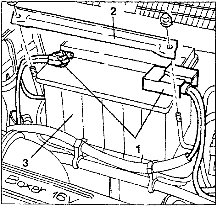
- If necessary, remove the battery acid drain tray.
Alternator
The alternator supplies electrical energy to the electronic control units and to the various services when the engine is running. It also charges the accumulator (battery) so that it can deliver current when the engine is stationary. The electric current is produced by a stator which "cuts" the magnetic field generated by a rotary coil (rotor). The rotor is integral with a pulley operated directly by the crankshaft through a belt. The contact brushes supply the rotor with the excitation current.
The alternate current generated by the alternator is rectified by the diodes and adjusted by the voltage regulator located on the alternator body. The electronic voltage regulator used is compact in size and it warrants constant voltage in all fields of operation of the engine, regardless of the changes in load and rpm. A cooling fan turns together with the pulley to prevent it from reaching dangerous temperatures that might adversely affect its operation. The alternator installed is of the type with claw terminals and collector rings; it is light and very compact. It is fastened to the engine by brackets, one of which is slotted to simplify tensioning of the drive belt (see GROUP 00).
CAUTION: The fan will correctly cool the alternator if it turns clockwise (seen from pulley side).
Removal/Refitting
- Disconnect the battery (-) terminal.
- Remove the radiator grille (see GROUP 70).
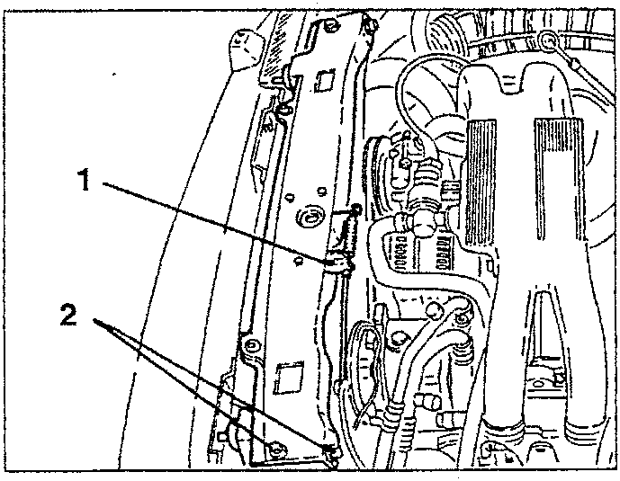
- Disconnect the opening cable from the bonnet lock.
- Slacken the fastening screws and remove the upper radiator crossmember.
Parts & tools for this job For 1994 Alfa Romeo 145/146
- PARTOil filterSearch: Alfa Romeo 145/146 1994 oil filter
- TOOLOil filter wrenchSearch: oil filter wrench
- FLUIDEngine oilSearch: Alfa Romeo 145/146 engine oil
Links open Amazon search results in a new tab. As an Amazon Associate I earn from qualifying purchases.