
LR3/Disco 3
Fuel Charging and Controls
Component Locations
GENERAL
The major components of the fuel charging and control system comprise an intake manifold, a fuel pump, a fuel rail and
six injectors. The fuel pump supplies fuel from the tank at a constant pressure, via a pipe routed along the underside of
the vehicle, to the fuel rail. The fuel rail distributes the fuel equally to each of the six injectors.
INTAKE MANIFOLD
The intake manifold is located on top of the engine. The manifold is manufactured from a composite material with metal
insert fixings. The manifold comprises a central chamber with six tracts leading to the inlet ports on the engine. For
additional information, refer to
Intake Air Distribution and Filtering
(303-12A Intake Air Distribution and Filtering - 4.0L)
FUEL PUMP
The submersible electric pump fuel pump and the fuel pressure regulator are a located in the fuel tank. A pump module
flange on top of the fuel tank allows access to the fuel pump for removal and installation.
The fuel pump, when running, outputs fuel at a constant pressure to the fuel rail. The pressure regulator controls the
Published : Oct 22, 2004
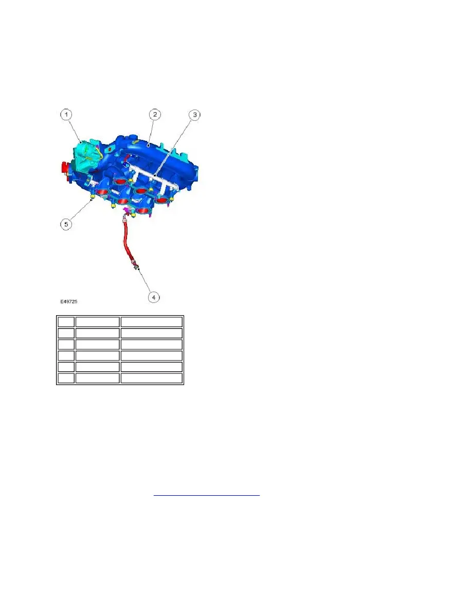
Item Part Number
Description
1
-
Throttle body
2
-
Intake manifold
3
-
Fuel rail
4
-
Fuel jump hose
5
-
Fuel injectors (6 of)