
Dis-assembly/re-assembly (page 2 of 2)
- Make
- Alfa Romeo
- Model
- 145/146 Electrical System Diagnosis Manual, Volume 3
- Year
- 1994–2001
- Section
- Electrical components
145 electrical system diagnosisDis-assembly/re-assembly · page 2 of 2
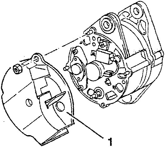
- Slacken the three fastening nuts and remove the protective cap.
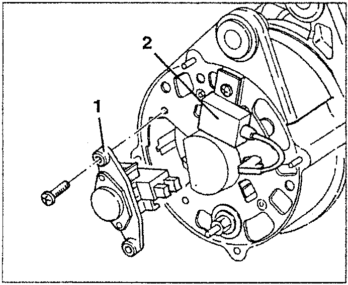
- Slacken the two fastening screws and remove the brush holder voltage regulator.
- Slacken the fastening screw, disconnect the electrical connection and remove the anti-disturbance condenser.
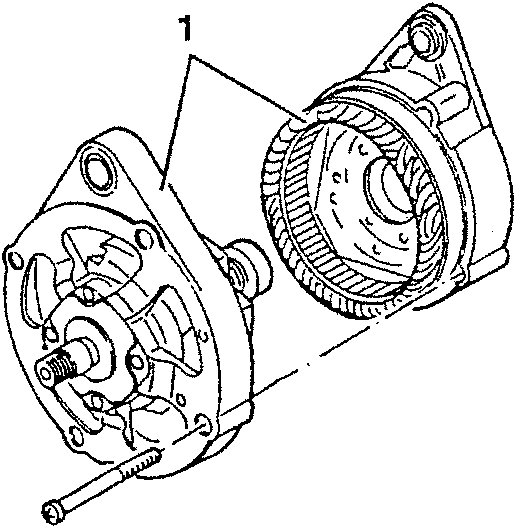
- Slacken the four fastening screws and separate the drive side support complete with rotor from the collector rings support complete with stator and rectifying unit.
- Slacken the three screws fastening the rectifying unit to the collector rings support.
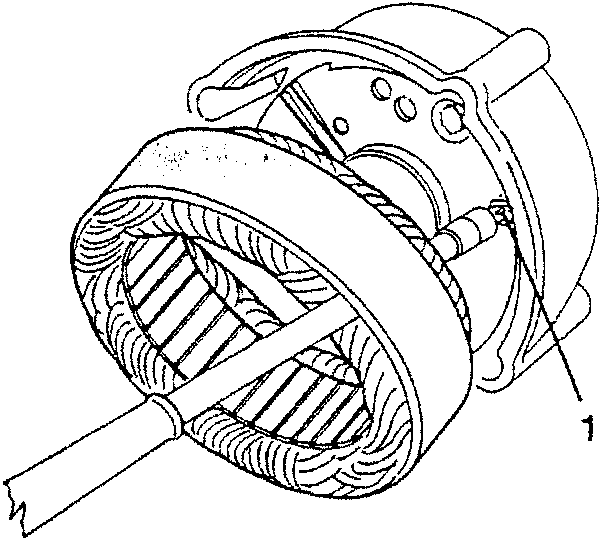
- Slacken the nut fastening the pin for connecting the positive terminal.
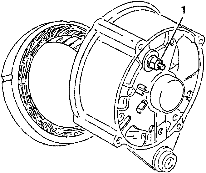
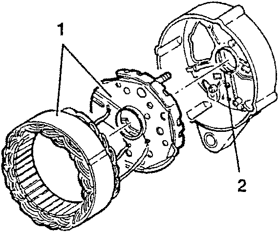
- Remove the stator complete with rectifying unit from the collector rings support.
- If necessary, remove the O-Ring from the collector rings support.
Parts & tools for this job For 1994 Alfa Romeo 145/146
- TOOLDigital multimeterSearch: automotive digital multimeter
- PARTAssorted fuse kitSearch: car fuse assortment kit
- TOOLWire crimper and connector kitSearch: wire crimper connector kit
Links open Amazon search results in a new tab. As an Amazon Associate I earn from qualifying purchases.