
Camshaft rear oil seal (page 5 of 5)
- Make
- Rover
- Model
- 200 Workshop Manual
- Year
- 1995–1999
- Section
- Repairs
Engine - L SeriesCamshaft rear oil seal · page 5 of 5
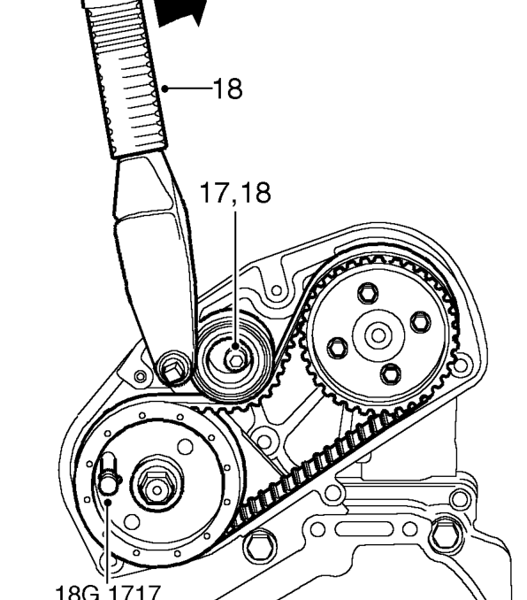
- Insert locking pin 18G 1717 through FIP drive gear and into hole in adapter plate.
NOTE: Locking pin may be a tight fit at this stage.
- Loosen timing belt tensioner pulley Allen bolt.
- Using a torque wrench fitted to tensioner pulley backplate, apply a clockwise, as viewed from rear of engine, torque loading of 6 Nm to drive belt. Maintain loading and tighten tensioner pulley Allen bolt to 44 Nm.
CAUTION: Do not exceed specified torque figure.
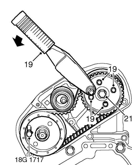
- Fit torque wrench to square hole in FIP timing belt drive gear as shown and apply an anti-clockwise as viewed from rear of engine, torque loading of 25 Nm. Maintain loading and tighten 4 bolts securing gear to 25 Nm.
- Remove FIP drive gear locking pin 18G 1717 and timing pin 18G 1523.
- Restrain camshaft gear using 18G 1521 and tighten bolt retaining FIP timing belt drive gear to 20 Nm + 90°.
- Rotate crankshaft clockwise 2 complete revolutions and fit timing pin 18G 1523.
CAUTION: Ensure pin is fully inserted into hole in flywheel.
- Check that camshaft gear timing mark is aligned with mark on back cover.
- Insert locking pin 18G 1717 through FIP drive gear and into hole in adapter plate.
CAUTION: To ensure injection pump timing is correct, locking pin must be a sliding fit. If pin is a tight fit, adjustment procedure must be repeated.
- On completion, remove timing pin 18G 1523 and locking pin 18G 1717.
- Fit timing belt upper cover. See this section.
- Fit FIP timing belt cover. See this section.
- Fit undertray. See BODY, Exterior fittings.
Parts & tools for this job For 1995 Rover 200
- PARTEngine gasket setSearch: Rover 200 1995 engine gasket set
- TOOLTorque wrenchSearch: 3/8 inch torque wrench
- TOOLFeeler gauge setSearch: feeler gauge set
Links open Amazon search results in a new tab. As an Amazon Associate I earn from qualifying purchases.