
Roof aerial – coupe
- Make
- Rover
- Model
- Coupé, Cabriolet & Tourer 200/400 Coupé, Cabriolet & Tourer Workshop Manual
- Section
- Repairs › Roof aerial – coupe
ElectricalRoof aerial – coupe
ROOF AERIAL – COUPE
Service Repair No. 86.50.18
Note: The aerial coaxial cable incorporates a 150 pf capacitor in series with signal line. This means that the cable would appear to be open circuit if tested with a continuity meter.
Remove
- Remove headlining, see BODY – Repairs.
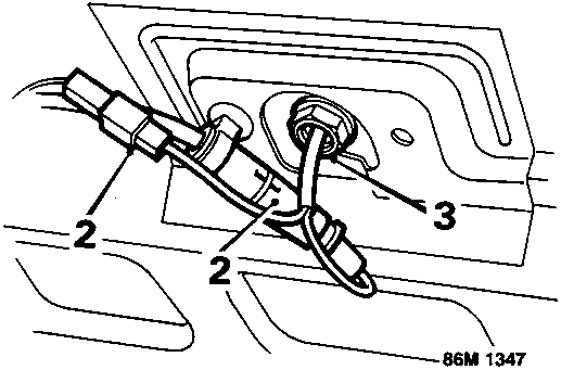
- Disconnect aerial coaxial lead and power lead.
- Remove nut securing aerial to roof panel.
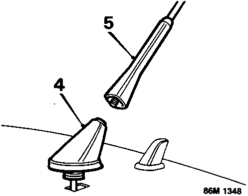
- Remove aerial.
- Remove aerial mast.
Refit
- Fit aerial mast.
- Fit aerial, ensuring that seal is correctly positioned, and secure with nut.
- Connect coaxial and power leads.
- Fit headlining, see BODY – Repairs.
RELAY MODULE
Service Repair No. 86.55.09
This relay module contains the relays for the Horn, Cigar lighter, Fog guard and Headlamp main/dip.
Remove
- Remove front console, see BODY – Repairs.
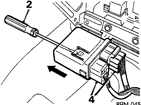
- Insert screwdriver to release catch.
- Slide relay module to left to release from retaining bracket.
- Release 2 multiplugs from relay module.
- Remove relay module.
Refit
- Position relay module.
- Connect multiplugs to relay module.
- Secure relay module to retaining bracket.
- Fit front console, see BODY – Repairs.
Parts & tools for this job For Rover Coupé, Cabriolet & Tourer
- TOOLDigital multimeterSearch: automotive digital multimeter
- PARTAssorted fuse kitSearch: car fuse assortment kit
- TOOLWire crimper and connector kitSearch: wire crimper connector kit
Links open Amazon search results in a new tab. As an Amazon Associate I earn from qualifying purchases.