
Remove
- Make
- Rover
- Model
- Coupé, Cabriolet & Tourer 200/400 Coupé, Cabriolet & Tourer Workshop Manual
- Section
- Repairs › Remove
ElectricalRemove
Service Repair No. 86.30.01
Note: This operation is unique for models fitted with a drivers airbag.
Remove
- Remove drivers airbag module, see SUPPLEMENTARY RESTRAINT SYSTEM – Repairs.
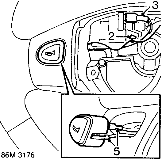
- Release earth connector from steering wheel base.
- Disconnect Lucar connector from connector block.
- Using a flat blade carefully ease switch from steering wheel.
- Disconnect 2 Lucar connectors from switch.
Refit
- Connect 2 Lucar connectors to horn push switch.
- Fit switch to steering wheel.
- Connect Lucar connector to connector block and secure earth connector to steering wheel base.
- Ensure horn switch harness is routed correctly and fit drivers airbag module, see SUPPLEMENTARY RESTRAINT SYSTEM – Repairs.
Parts & tools for this job For Rover Coupé, Cabriolet & Tourer
- TOOLDigital multimeterSearch: automotive digital multimeter
- PARTAssorted fuse kitSearch: car fuse assortment kit
- TOOLWire crimper and connector kitSearch: wire crimper connector kit
Links open Amazon search results in a new tab. As an Amazon Associate I earn from qualifying purchases.