
Subframe - front (page 6 of 6)
- Make
- MG
- Model
- MGF Factory Workshop Manual
- Year
- 1995–2000
- Section
- Repairs
SuspensionSubframe - front · page 6 of 6
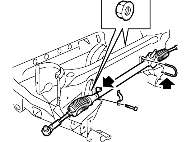
- Remove 2 nuts and bolts and ’U’ bolt securing steering rack to subframe.
- Remove steering rack, collect ’U’ bolt and clamp.
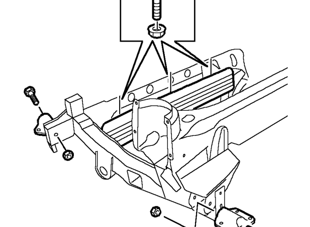
- Remove nut and bolt securing LH front subframe mounting and collect mounting.
- Remove nut and bolt securing LH rear subframe mounting and collect mounting.
- Repeat process for RH subframe mountings.
- Remove 3 nuts and bolts securing splash guard to subframe and remove splash guard.
Refit
- Position splash guard, fit nuts and bolts and tighten to 8 Nm.
- Position LH rear subframe mounting fit nut and bolt and tighten to 100 Nm.
- Position LH front subframe mounting, fit nut and bolt and tighten to 100 Nm.
- Repeat above for RH mountings.
- Position steering rack to subframe fit ’U’ bolt. Clamp and tighten nuts and bolts to 22 Nm.
- Position lower arm in subframe, fit bolts and tighten to 85 Nm.
- Fit grommet to subframe.
- Fit top arm pivot shaft thrust washers and seals.
- Position top arm and knuckle joint ball pin in subframe, and fit pivot shaft.
- Fit retaining plate to pivot shaft and tighten bolts to 10 Nm.
- Fit nuts securing pivot shaft and tighten to 74 Nm.
- Position LH hydragas unit in subframe and fit retaining plate and ABS sensor lead bracket.
- Fit retaining plate bolts and tighten to 25 Nm.
- Repeat suspension build process for other side.
- Fit LH crash can, fit bolts and tighten to 22 Nm.
- Clean hub assembly and suspension arms.
- Position hub assembly to suspension arms and engage ball joints.
- Using a new lock washer, fit nut to top ball joint and tighten to 54 Nm and secure lock washer.
- Ensure bottom ball joint pin is fully engaged in hub.
- Fit nut and bolt securing bottom ball joint and tighten to 45 Nm.
- Repeat above for other side.
- Connect track rod ends to hubs, fit nuts and tighten to 30 Nm.
- Position anti-roll bar, fit clamps and bolts and tighten to 22 Nm.
- Align anti-roll bar links to anti-roll bar fit nuts and bolts and tighten to 35 Nm.
Parts & tools for this job For 1995 MG MGF
- TOOLCoil spring compressorSearch: coil spring compressor
- TOOLBall joint separatorSearch: ball joint separator
- PARTFront shock absorbersSearch: MG MGF 1995 front shock absorbers
Links open Amazon search results in a new tab. As an Amazon Associate I earn from qualifying purchases.