
Components (page 2 of 4)
- Make
- Rover
- Model
- 600 Rover 600 Repair Manual - Volumes 1 and 2 - 2nd Edition
- Section
- Repairs
Automatic gearboxComponents · page 2 of 4
Note: Clean all parts thoroughly in solvent or cleaner and dry with compressed air.
Blow out all passages.
When removing the right side cover, replace the following:
- Right side cover gasket
- Lock washers
- Gearbox housing gasket
- 'O' rings
- Each shaft locknut and conical spring washer
- Sealing washers
- Remove the eleven bolts securing the right side cover, then remove the right side cover, discard gasket.
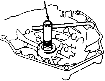
- Slide tool onto the mainshaft.
- Engage the parking brake pawl with the parking gear.
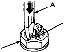
A Chisel
B Lock tab
C Locknut
CAUTION: Always wear safety glasses.
- Cut the lock tabs of each shaft locknut using a chisel as shown. Then remove the locknuts and conical spring washers from each shaft.
Note: Keep all of the chiselled particles out of the gearbox.
Mainshaft locknut has left-hand thread.
- Clean the old locknuts; they are used to install the press fit idler gears on the mainshaft and secondary shaft and the parking gear on the countershaft.
- Remove tool from the mainshaft after removing the locknuts.
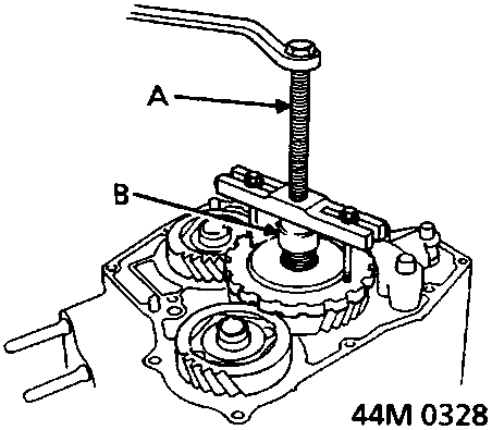
A Suitable puller
B Thrust button
- Using a suitable puller, remove parking gear from countershaft.
- Using a suitable puller, remove idler gears from mainshaft and secondary shaft.
- Remove the countershaft idler gear, needle bearing, thrust needle bearing, and thrust washer from the countershaft.
- Remove the parking brake pawl, spring, shaft, and stopper from the housing.
- Remove the throttle control lever and spring from the throttle control shaft.
- Remove the fluid cooler pipe mounting bolt from the bracket.
- Remove the gearbox housing mounting bolts.
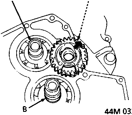
A Reverse idler gear
B Countershaft
C Mainshaft
Parts & tools for this job For Rover 600
- PARTTransmission filter kitSearch: Rover 600 transmission filter kit
- FLUIDAutomatic transmission fluidSearch: Rover automatic transmission fluid
- TOOLFluid transfer pumpSearch: fluid transfer pump
Links open Amazon search results in a new tab. As an Amazon Associate I earn from qualifying purchases.