
See ’R65’, Adjustments. (page 7 of 11)
- Make
- Rover
- Model
- 200 Workshop Manual
- Year
- 1995–1999
- Section
- Repairs
Engine - K16See ’R65’, Adjustments. · page 7 of 11
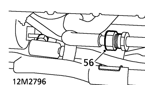
- Loosen union and disconnect compressor pipe from evaporator pipe.
CAUTION: To prevent damage to air conditioning pipes and components use two spanners when loosening or tightening unions.
- Remove and discard ’O’ ring from compressor pipe.
- Position evaporator pipe aside.
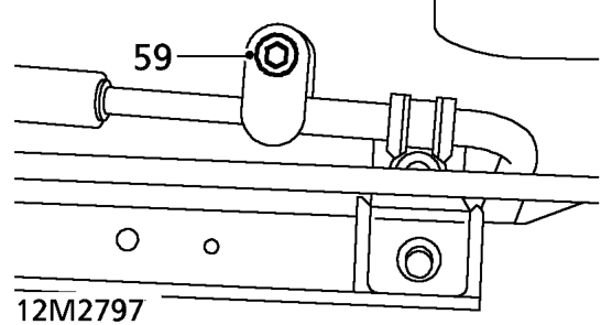
- Remove bolt securing compressor pipe to condenser pipe.
- Release compressor pipe from condenser pipe and discard ’O’ ring.
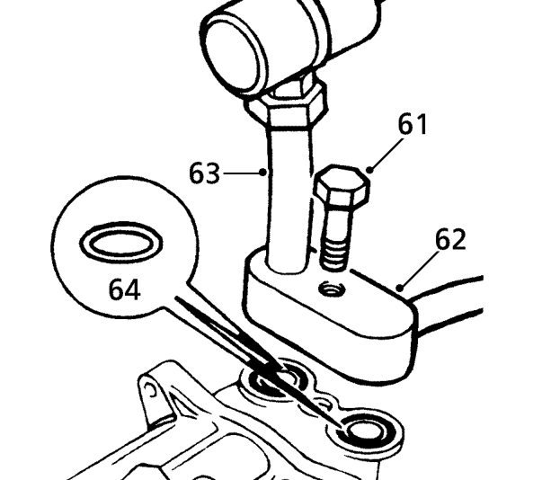
- Remove bolt securing air conditioning pipe union to compressor.
- Release air conditioning pipe union from compressor.
- Remove air conditioning pipes.
- Remove and discard 2 ’O’ rings from compressor.
CAUTION: Immediately cap all air conditioning pipes and compressor to prevent ingress of dirt and moisture into the system.
Parts & tools for this job For 1995 Rover 200
- PARTEngine gasket setSearch: Rover 200 1995 engine gasket set
- TOOLTorque wrenchSearch: 3/8 inch torque wrench
- TOOLFeeler gauge setSearch: feeler gauge set
Links open Amazon search results in a new tab. As an Amazon Associate I earn from qualifying purchases.