
Test (page 3 of 9)
- Make
- Rover
- Model
- 600 Rover 600 Repair Manual - Volumes 1 and 2 - 2nd Edition
- Section
- Repairs
Automatic gearboxTest · page 3 of 9
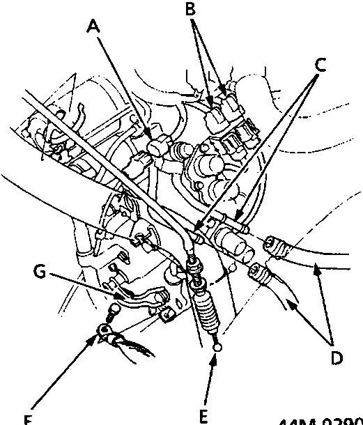
A Mainshaft speed sensor harness connector
B Solenoid valve harness connectors
C Fluid cooler hose connections
D Fluid hoses
E Throttle control cable end
F Gearbox earth cable
G Throttle control lever
- Disconnect the earth cable from the gearbox.
- Disconnect the lock – up control solenoid valve and shift control solenoid valve harness connectors.
- Disconnect the throttle control cable from the throttle control lever.
- Disconnect the mainshaft speed sensor harness connector.
- Disconnect the fluid cooler hoses. Plug the ends of the hoses to prevent fluid from flowing out.
Note: Check for any signs of leakage at the hose connections.
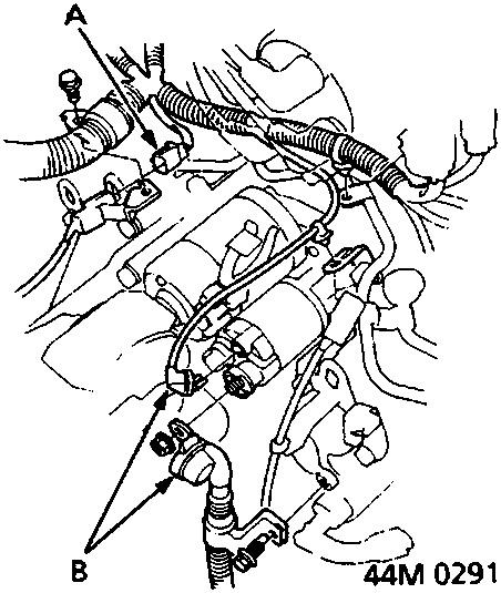
A Countershaft speed sensor harness connector
B Starter motor cables
- Remove the starter motor cables.
- Disconnect the countershaft speed sensor harness connector.
- Remove the harness stay and clamp.
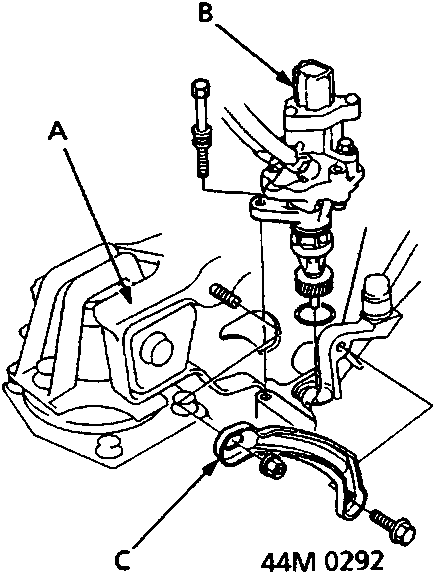
A Engine rear mounting
B Vehicle speed/power steering speed sensor
C Rear stiffener
Parts & tools for this job For Rover 600
- PARTTransmission filter kitSearch: Rover 600 transmission filter kit
- FLUIDAutomatic transmission fluidSearch: Rover automatic transmission fluid
- TOOLFluid transfer pumpSearch: fluid transfer pump
Links open Amazon search results in a new tab. As an Amazon Associate I earn from qualifying purchases.