
Test (page 6 of 9)
- Make
- Rover
- Model
- 600 Rover 600 Repair Manual - Volumes 1 and 2 - 2nd Edition
- Section
- Repairs
Automatic gearboxTest · page 6 of 9
- Remove and discard the right damper pinch bolt, then separate the damper fork and damper.
- Remove and discard the Patchlok bolts and self – locking nuts, then remove the right radius rod.
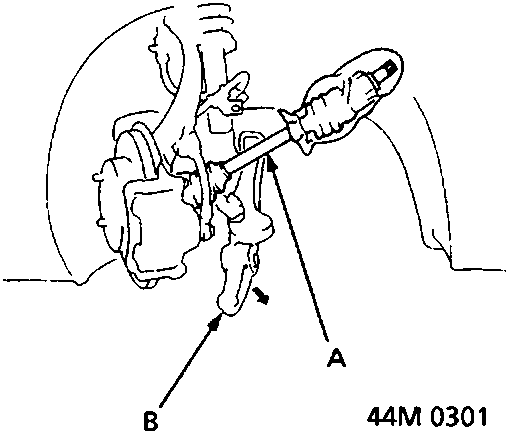
A Driveshaft
B Lower arm
- Lower the right lower arm and move the right driveshaft to front side of the car as shown.
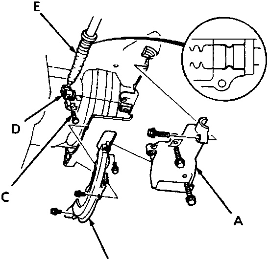
A Selector cable cover
B Torque converter cover
C Lock bolt
D Control lever
E Selector cable
- Remove the torque converter cover and selector cable cover.
- Remove the lock bolt securing the control lever, then remove the selector cable with the control lever.
CAUTION: Take care not to bend the shift cable when removing it.
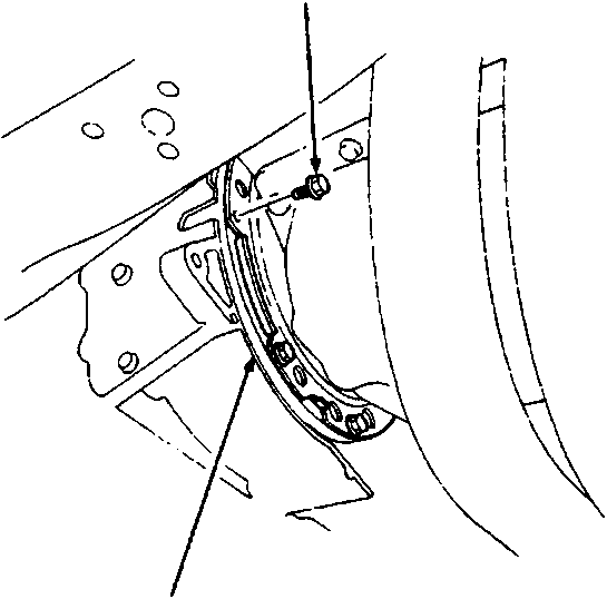
A Drive plate bolt
B Drive plate
- Remove the eight drive plate bolts one at a time while rotating the crankshaft pulley.
Note: If necessary, remove the spark plugs when rotating the crankshaft pulley.
Parts & tools for this job For Rover 600
- PARTTransmission filter kitSearch: Rover 600 transmission filter kit
- FLUIDAutomatic transmission fluidSearch: Rover automatic transmission fluid
- TOOLFluid transfer pumpSearch: fluid transfer pump
Links open Amazon search results in a new tab. As an Amazon Associate I earn from qualifying purchases.