
Test (page 7 of 9)
- Make
- Rover
- Model
- 600 Rover 600 Repair Manual - Volumes 1 and 2 - 2nd Edition
- Section
- Repairs
Automatic gearboxTest · page 7 of 9
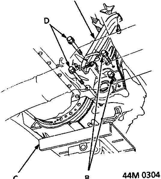
- A Inlet manifold bracket
- B Engine rear mounting bolts
- C Gearbox hoist
- D Gearbox housing mounting bolts
- Place a gearbox hoist under the gearbox, and raise the gearbox just enough to take weight off the mounting.
- Remove the inlet manifold bracket.
- Remove the gearbox housing mounting bolts and engine rear mounting bolts.
- Pull the gearbox away from the engine until it clears the 14 mm dowel pins, then lower it on the gearbox hoist.
Parts & tools for this job For Rover 600
- PARTTransmission filter kitSearch: Rover 600 transmission filter kit
- FLUIDAutomatic transmission fluidSearch: Rover automatic transmission fluid
- TOOLFluid transfer pumpSearch: fluid transfer pump
Links open Amazon search results in a new tab. As an Amazon Associate I earn from qualifying purchases.