
Reassemble (page 8 of 11)
- Make
- Rover
- Model
- 600 Rover 600 Repair Manual - Volumes 1 and 2 - 2nd Edition
- Section
- Repairs
Automatic gearboxReassemble · page 8 of 11
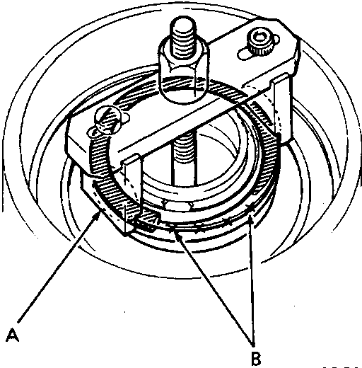
CAUTION: If tool is placed over an area of the spring retainer which is unsupported by the return spring, the retainer may be damaged.
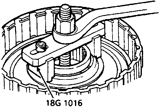
Note: The following operations are for all clutches.
- Compress the return spring.
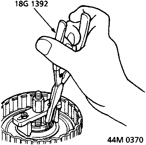
- Remove the snap ring using tools. Then remove tools, the spring retainer and return spring.
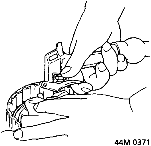
- Cover clutch drum and fluid outlet passage with clean, lint free cloth and apply low pressure air to fluid inlet passage to expel clutch piston.
WARNING: Do not cover fluid outlet passage with the finger, fluid can be forced through the skin.
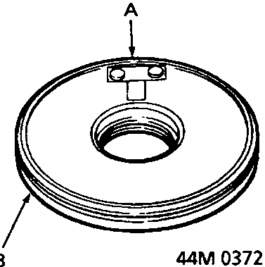
- Inspect the piston for a loose check valve, if the check valve is loose, replace the piston.
- Check snap rings for distortion.
- Check disc and return springs for distortion.
- Check thickness of clutch plates:
3rd/4th clutch = 2.30 mm
1st clutch = 2.00 mm
2nd clutch = 2.60 mm
1st hold clutch = 2.00 mm - Check thickness of clutch discs:
3rd/4th clutch = 1.94 mm
1st clutch = 1.94 mm
2nd clutch = 1.94 mm
1st hold clutch = 1.94 mm - Replace plates and discs in sets only.
- Ensure all fluid passages are clear.
Parts & tools for this job For Rover 600
- PARTTransmission filter kitSearch: Rover 600 transmission filter kit
- FLUIDAutomatic transmission fluidSearch: Rover automatic transmission fluid
- TOOLFluid transfer pumpSearch: fluid transfer pump
Links open Amazon search results in a new tab. As an Amazon Associate I earn from qualifying purchases.