
Remove (page 10 of 10)
- Make
- Rover
- Model
- 600 Rover 600 Repair Manual - Volumes 1 and 2 - 2nd Edition
- Section
- Repairs
Automatic gearboxRemove · page 10 of 10
- Remove the original locknuts, then install new conical spring washers and new locknuts on each shaft.
CAUTION: Install the conical spring washers in the direction shown.
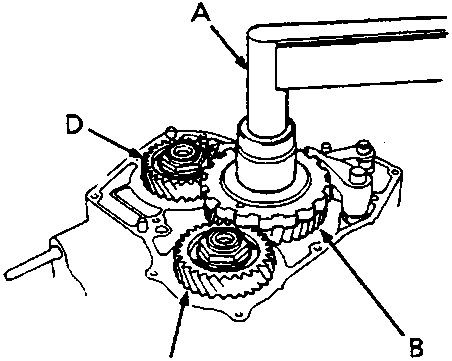
- A Torque wrench
- B Parking gear
- C Secondary shaft idler gear
- D Mainshaft idler gear
- Tighten the locknuts to 170 Nm.
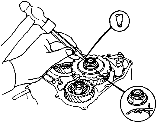
- Stake each locknut into its shaft using a 3.5 mm punch.
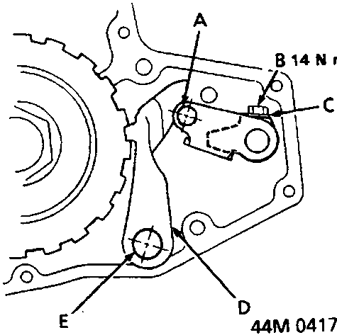
- A Parking brake lever roller pin
- B Lock bolt
- C Lock washer
- D Parking brake pawl
- E Parking brake pawl shaft
- Set the parking brake lever in the P position, then verify that the parking brake pawl engages the parking gear.
- If the pawl does not engage fully, check the parking brake pawl stopper clearance.
- Tighten the lock bolt to 14 Nm and bend the lock tab against the bolt head.
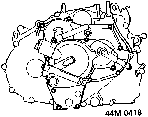
- Install the right side cover, tighten bolts to 12 Nm.
- Install the fluid cooler pipes, use new sealing washers and tighten bolts to 29 Nm.
- Install the fluid level gauge.
Parts & tools for this job For Rover 600
- PARTTransmission filter kitSearch: Rover 600 transmission filter kit
- FLUIDAutomatic transmission fluidSearch: Rover automatic transmission fluid
- TOOLFluid transfer pumpSearch: fluid transfer pump
Links open Amazon search results in a new tab. As an Amazon Associate I earn from qualifying purchases.