
Remove (page 6 of 10)
- Make
- Rover
- Model
- 600 Rover 600 Repair Manual - Volumes 1 and 2 - 2nd Edition
- Section
- Repairs
Automatic gearboxRemove · page 6 of 10
- Install the control shaft in the housing with the control shaft and manual valve together.
- Install the detent arm and arm shaft in the main valve body, then hook the detent spring to the detent arm.
- Install the secondary valve body, servo separator plate and servo valve body with seven bolts; tighten bolts to 12 Nm.
- Install the oil feed pipe in the servo valve body, then install the 4th accumulator cover with three bolts; tighten bolts to 12 Nm.
- Install the fluid strainer with two bolts; tighten bolts to 12 Nm.
- Install the servo detent base with two bolts and new lock washers; tighten bolts to 12 Nm.
- Install the 1st/2nd accumulator body and accumulator body cover with six bolts; tighten bolts to 12 Nm.
- Install two oil feed pipes in the main valve body and the pipe in the servo body.
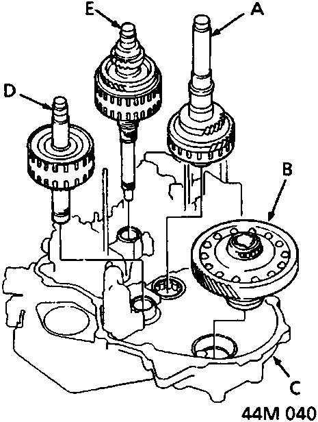
- Countershaft sub – assembly
- Differential assembly
- Torque converter housing
- Secondary shaft sub – assembly
- Mainshaft sub – assembly
- Install the differential assembly, countershaft sub – assembly, mainshaft sub – assembly, and secondary shaft sub – assembly in the torque converter housing.
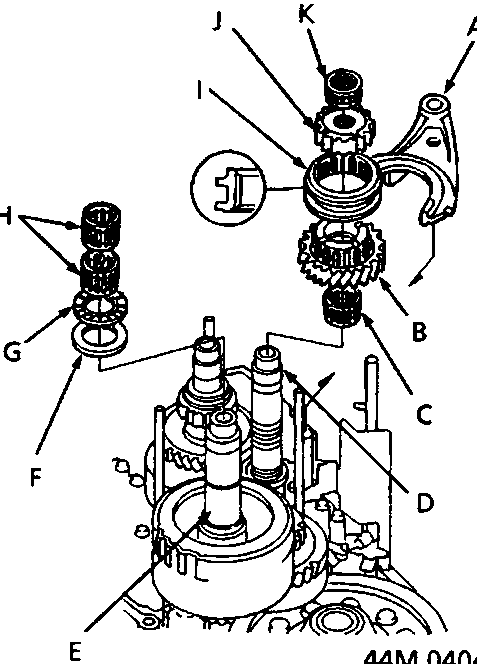
- Shift fork
- Countershaft 4th gear
- Needle bearing
- Countershaft
- Secondary shaft
- Splined washer
- Thrust needle bearing
- Needle bearings
- Reverse selector
- Reverse selector hub
- Needle bearing
- Install the splined washer, thrust needle bearing and needle bearings on the secondary shaft.
- Install the needle bearings, countershaft 4th gear, reverse selector hub, and reverse selector with the shift fork on the countershaft.
CAUTION: Groove in reverse selector must be towards torque converter housing.
Parts & tools for this job For Rover 600
- PARTTransmission filter kitSearch: Rover 600 transmission filter kit
- FLUIDAutomatic transmission fluidSearch: Rover automatic transmission fluid
- TOOLFluid transfer pumpSearch: fluid transfer pump
Links open Amazon search results in a new tab. As an Amazon Associate I earn from qualifying purchases.