
Remove (page 5 of 10)
- Make
- Rover
- Model
- 600 Rover 600 Repair Manual - Volumes 1 and 2 - 2nd Edition
- Section
- Repairs
Automatic gearboxRemove · page 5 of 10
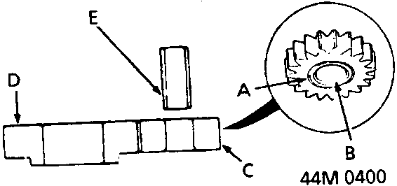
A Groove
B Chamfer
C Oil pump driven gear
D Oil pump drive gear
E Oil pump driven gear shaft
- Coat all parts with transmission fluid.
- Replace the following:
- 'O' rings
- Lock washers
- Gaskets
- Locknuts and conical spring washers
- Sealing washer
Torque the M6 bolts to 12Nm and the M8 bolts to 18Nm.
- Install the main separator plate with three dowel pins on the torque converter housing. Then install the oil pump gears and oil pump driven gear shaft. Install the oil pump driven gear with its grooved and chamfered side facing downwards.
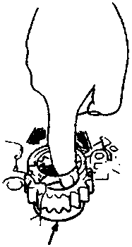
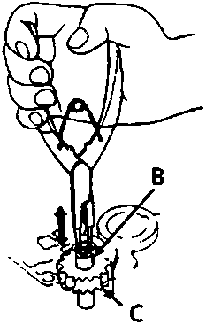
A Oil pump drive gear
B Oil pump driven gear shaft
C Oil pump driven gear
- Install the main valve body with four M8 bolts. Make sure the oil pump drive gear rotates smoothly in the normal operating direction and oil pump driven gear shaft moves smoothly in the axial and normal operating directions.
- If the oil pump drive gear and oil pump driven gear shaft do not move freely, loosen the main valve body bolts, realign the oil pump driven gear shaft, and then retighten to 18 Nm. Do not fit M6 bolt at this stage.
CAUTION: Failure to align the oil pump driven gear shaft correctly will result in a seized oil pump drive gear or oil pump driven gear shaft.
- Install the stator shaft and stopper shaft.
- Install the two dowel pins, torque converter check valve and torque converter check valve spring in the main valve body.
- Install the regulator valve body with the M6 bolt on the main valve body, tighten bolt to 12 Nm.
- Install the two dowel pins and throttle separator plate on the regulator valve body, then install the throttle valve body with seven bolts; tighten bolts to 12 Nm.
- Install the secondary separator plate with two dowel pins on the main valve body.
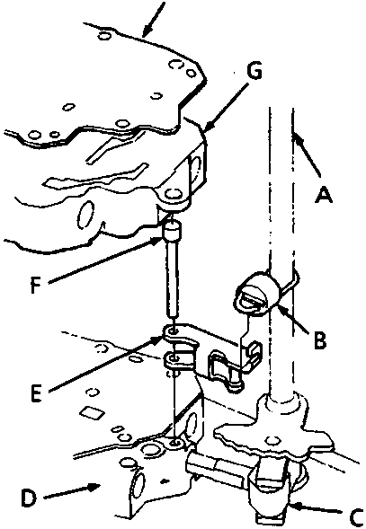
A Control shaft
B Detent spring
C Manual valve
D Main valve body
E Detent arm
F Detent arm shaft
G Secondary valve body
H Servo separator plate
Parts & tools for this job For Rover 600
- PARTTransmission filter kitSearch: Rover 600 transmission filter kit
- FLUIDAutomatic transmission fluidSearch: Rover automatic transmission fluid
- TOOLFluid transfer pumpSearch: fluid transfer pump
Links open Amazon search results in a new tab. As an Amazon Associate I earn from qualifying purchases.