
Throttle position (tp) sensor - KV6
- Make
- Rover
- Model
- 800 Workshop Manual
- Year
- 1996–1999
- Section
- Repairs › Throttle position (tp) sensor - KV6
‹ Prev Crankshaft position (ckp) sensor - KV6 - automatic gearboxNext › Manifold absolute pressure (map) sensor - KV6
Engine management system - MEMSThrottle position (tp) sensor - KV6
THROTTLE POSITION (TP) SENSOR - KV6
Service repair no - 18.30.17
Remove
- Disconnect battery earth lead.
- Remove air cleaner. See this section.
- Remove engine acoustic cover. See BODY, Repairs.
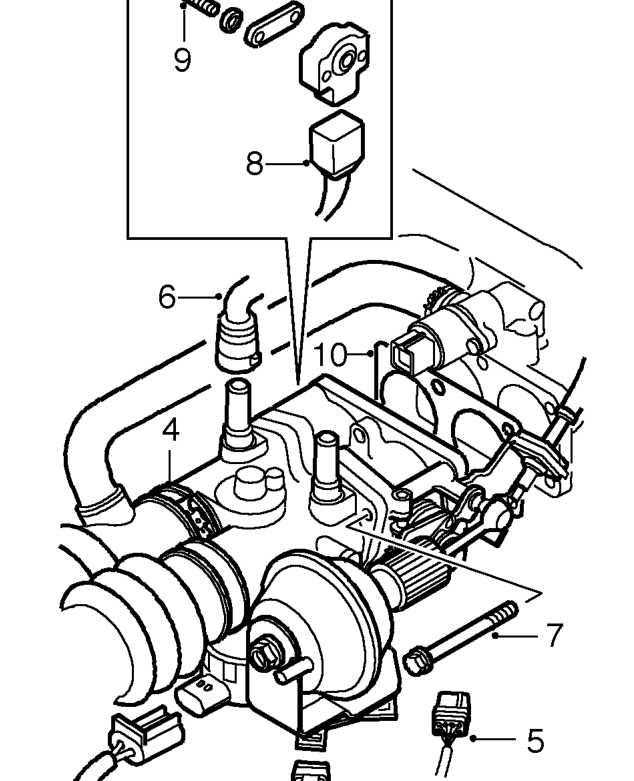
- Release clip securing intake hose to throttle housing and move hose aside.
- Disconnect engine harness multiplugs from bracket on throttle housing.
- Disconnect 2 vacuum hoses from throttle housing.
- Remove 5 bolts securing throttle housing to manifold chamber.
- Release throttle housing from manifold chamber and disconnect multiplug from throttle position sensor.
- Remove 2 screws and remove throttle position sensor.
- Remove throttle housing gasket.
Refit
- Clean mating faces of throttle housing and throttle position sensor.
- Fit throttle position sensor. Ensure that during fitting the machined flat on the throttle spindle is aligned with the mating portion of the throttle position sensor.
CAUTION: The throttle position sensor can easily be damaged during fitting. When pressing the sensor onto throttle spindle use fingers only.
- Rotate throttle position sensor anti- clockwise direction to align fixing holes.
CAUTION: Do not rotate sensor in a clockwise direction. Ensure sensor is not rotated beyond its internal stops.
- Fit and tighten sensor securing screws.
- Connect throttle position sensor multiplug.
- Fit throttle housing gasket.
- Position throttle housing and tighten bolts to 10 Nm.
- Connect vacuum hoses to throttle housing.
- Connect engine harness multiplugs to bracket on throttle housing.
- Position intake hose to throttle housing and secure clip.
- Fit air cleaner. See this section.
- Fit engine acoustic cover. See BODY, Repairs.
- Connect battery earth lead.
‹ Prev Crankshaft position (ckp) sensor - KV6 - automatic gearboxNext › Manifold absolute pressure (map) sensor - KV6
Parts & tools for this job For 1996 Rover 800
- TOOLOBD2 scannerSearch: OBD2 scanner
- TOOLDigital multimeterSearch: automotive digital multimeter
- TOOLBack-probe test leadsSearch: back probe test leads
Links open Amazon search results in a new tab. As an Amazon Associate I earn from qualifying purchases.