
Removing/refitting arming bracket
- Make
- Alfa Romeo
- Model
- 145/146 Factory Service Manual
- Year
- 1994–1999
- Section
- Internal trim › Removing/refitting arming bracket
The lever, pulled by spring I acts as a percussion head to trigger charge D. The gas freed by combustion, which is for the most part harmless nitrogen, pushes piston B along tube A. The psiton taws the steel cable C behind it shich is fixed to the other end of the seat belt rewinding device, causing it to rewind to a degree suited to the variable factors of vehicle type and speed of impact. Following its intervention the seat belt is locked thus signalling that the device has in fact intervened.
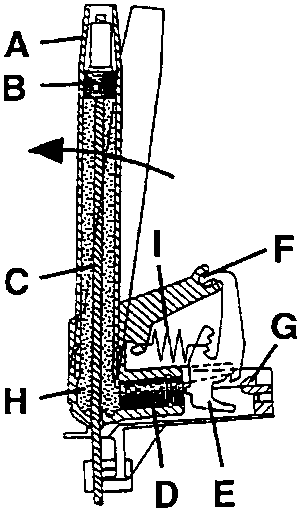
To prevent the device from being triggered if an inert reel is removed, it is fitted with a security or arming system which locks the deceleration sensor/trigger mechanism.
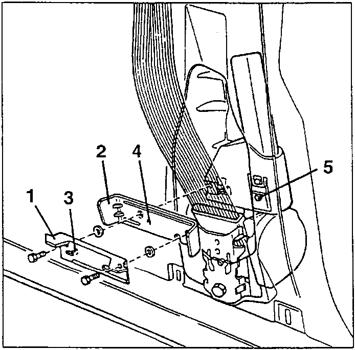
- Outer arming bracket
- Inner bracket
- Centering pin
- Centering hole
- Inner bracket retainer pin
REMOVING/REFITTING ARMING BRACKET
When remoing/refitting the arming bracket, the sequence given below must be strictly adhered to.
WARNING: The removal of the arming bracket is the only way to prevent the pyrotechnic device from being triggered accidentally. This procedure must therefore be carried out every time mechanical or body servicing operations on the car might cause the device to be operated by accident; the arming rod must absolutely be removed to obtain the necessary security conditions before proceeding with removal of the inertia reel - belt pretensioner unit, and also when handling and refitting. The arming bracket must ALWAYS be re-fitted ONLY WITH THE INERTIA REEL - PRETENSIONER UNIT FITTED ON THE CAR, in order to prevent any harm to personnel.
NOTE: The arming bracket comprises an inner bracket and an outer arming bracket which improve fastening the inertia real-pretensioner unit to the pillar.
- Remove the sill (see specific paragraph).
- Remove the side panel (see specific paragraph).
- check that the paint applied to the inertia real/pre-tensioner unit is intact meaning that the components have been installed correctly; check the way this paint is applied to restore the same conditions after assembly of the arming bracket.
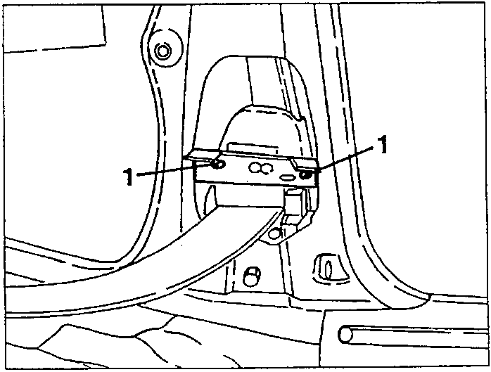
- Slacken the two fastening screws and remove the outer arming bracket.
Parts & tools for this job For 1994 Alfa Romeo 145/146
- TOOLTrim removal tool kitSearch: trim removal tool kit
- PARTTouch-up paintSearch: Alfa Romeo touch up paint
- PARTPanel clip assortmentSearch: Alfa Romeo panel clips assortment
Links open Amazon search results in a new tab. As an Amazon Associate I earn from qualifying purchases.