
Steering column switch assembly
- Make
- Rover
- Model
- 200 Workshop Manual
- Year
- 1995–1999
- Section
- Repairs › Steering column switch assembly
ElectricalSteering column switch assembly
STEERING COLUMN SWITCH ASSEMBLY
Service repair no - 86.65.64
Remove
- Remove rotary coupler. See this section.
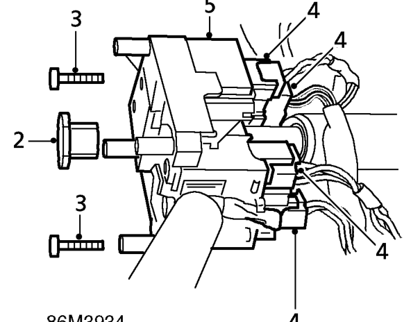
- Remove indicator cancelling cam from column.
- Remove 2 screws securing switch assembly to steering column.
- Release switch assembly from column and disconnect 4 multiplugs.
- Remove switch assembly. Do not carry out further dismantling if component is removed for access only.
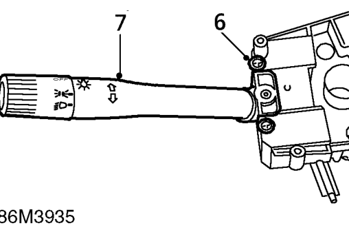
- Remove 2 screws securing direction indicator/headlamp stalk to switch assembly.
- Remove direction indicator/headlamp stalk from switch assembly.
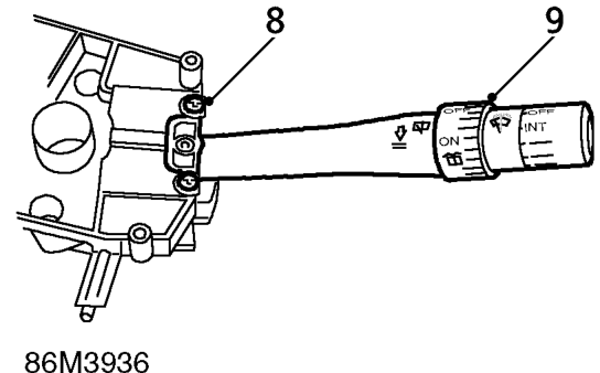
- Remove 2 screws securing wash/wipe stalk to switch assembly.
- Remove wash/wipe stalk from switch assembly.
- Fit wash/wipe stalk to switch assembly and secure with screws.
- Fit direction indicator/headlamp stalk to switch assembly and secure with screws.
Refit
- Position switch assembly to steering column, connect multiplugs and tighten retaining screws.
- Fit direction indicator cancelling cam to steering column.
- Fit rotary coupler. See this section.
Parts & tools for this job For 1995 Rover 200
- TOOLOBD2 scannerSearch: OBD2 scanner
- TOOLDigital multimeterSearch: automotive digital multimeter
- TOOLBack-probe test leadsSearch: back probe test leads
Links open Amazon search results in a new tab. As an Amazon Associate I earn from qualifying purchases.