
All models (page 2 of 3)
- Make
- Rover
- Model
- 600 Repair Manual Supplement
- Year
- 1993–1999
- Section
- Repairs
Engine - L SeriesAll models · page 2 of 3
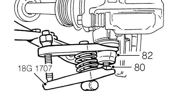
- Screw a 12 mm nut onto ball pin ends. If necessary, apply penetrating oil to joints.
- Break taper joints using tool 18G 1707 and separate ball pins from lower arms.
CAUTION: Ensure cross-bar on tool is at right angles (as shown). Be careful not to damage ball joint boots.
- Release lower arm ball pins from hub.
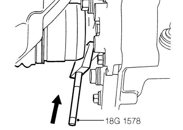
- Insert tool 18G 1578 between drive shaft and gearbox to disengage drive shaft circlip from differential by pulling on the inboard housing.
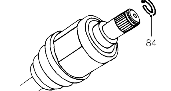
- Remove and discard circlips from drive shafts.
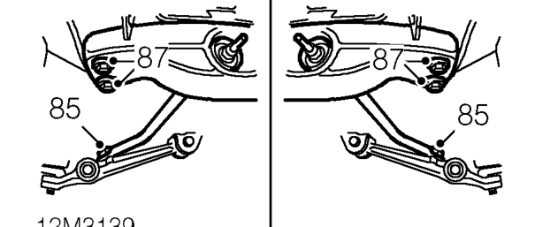
- Remove 2 bolts securing LH and RH radius arms to lower arms.
- Remove engine lower steady bar. See this section.
- Remove 4 bolts securing front beam and remove using assistance.
Parts & tools for this job For 1993 Rover 600
- PARTEngine gasket setSearch: Rover 600 1993 engine gasket set
- TOOLTorque wrenchSearch: 3/8 inch torque wrench
- TOOLFeeler gauge setSearch: feeler gauge set
Links open Amazon search results in a new tab. As an Amazon Associate I earn from qualifying purchases.