
Crankshaft pulley
- Make
- Rover
- Model
- 600 Repair Manual Supplement
- Year
- 1993–1999
- Section
- Repairs › Crankshaft pulley
Engine - L SeriesCrankshaft pulley
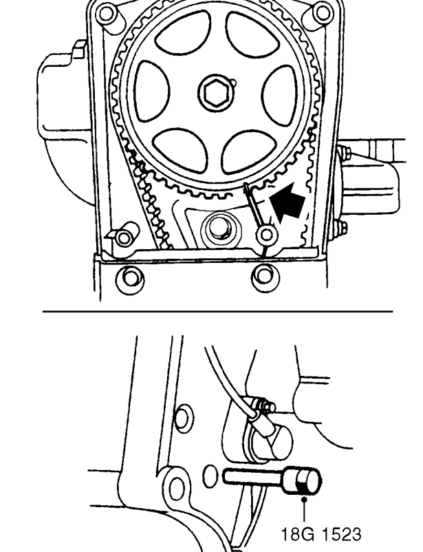
- Rotate crankshaft 2 turns clockwise and fit timing pin 18G 1523, ensuring pin is fully inserted in hole in flywheel.
- Check that camshaft gear timing mark is aligned with mark on back cover.
- Insert locking pin 18G 1717 through hole in injection pump drive gear and into hole in mounting plate.
CAUTION: To ensure that injection pump timing is correct, locking pin must be a sliding fit. If pin is a tight fit, adjustment procedure must be repeated.
- On completion, remove timing pin 18G 1523 and locking pin 18G 1717.
- Fit camshaft timing belt upper front cover. See this section.
- Fit fuel injection pump timing belt cover. See this section.
- Fit front centre underbelly panel. See BODY, Exterior fittings.
CRANKSHAFT PULLEY
Service repair no - 12.21.01
Remove
- Remove auxiliary drive belt. See ELECTRICAL, Adjustments.
- Remove RH front road wheel.
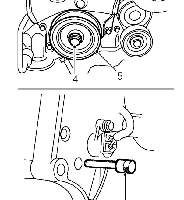
- Insert tool 18G 1523 through hole in gearbox mounting plate, hold tool in contact with flywheel and rotate crankshaft clockwise until tool can be felt to enter hole in flywheel.
CAUTION: Never use the camshaft gear, gear retaining bolt or timing belt to rotate the crankshaft.
- Remove bolt securing crankshaft pulley.
- Remove crankshaft pulley.
Parts & tools for this job For 1993 Rover 600
- PARTEngine gasket setSearch: Rover 600 1993 engine gasket set
- TOOLTorque wrenchSearch: 3/8 inch torque wrench
- TOOLFeeler gauge setSearch: feeler gauge set
Links open Amazon search results in a new tab. As an Amazon Associate I earn from qualifying purchases.