
Alternator - ’l’ series with air conditioning (page 2 of 3)
- Make
- Rover
- Model
- 200 Workshop Manual
- Year
- 1995–1999
- Section
- Repairs
ElectricalAlternator - ’l’ series with air conditioning · page 2 of 3
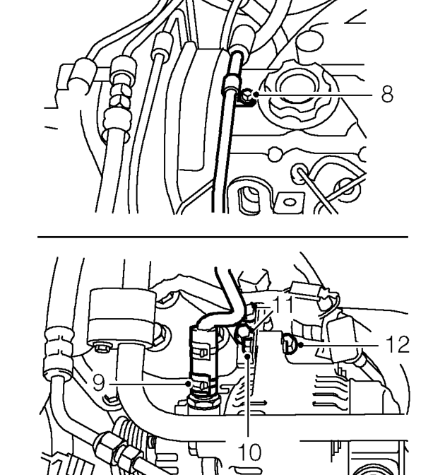
- Remove bolt securing brake servo vacuum pipe to camshaft cover.
- Release clip and disconnect vacuum hose from vacuum pump.
- Remove bolt securing alternator to top mounting bracket.
- Remove 2 bolts securing alternator top mounting bracket to coolant outlet elbow and remove mounting bracket.
- Remove bolt securing dipstick tube to coolant outlet elbow.
- Fit wooden block to jack and position jack to support engine.
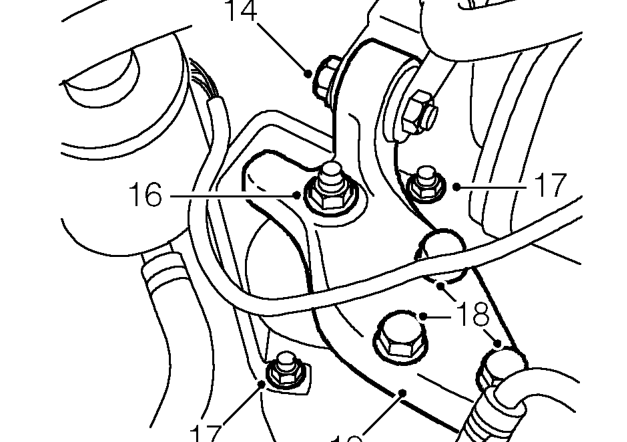
- Loosen through bolt securing RH steady bar to body.
- Remove through bolt securing RH steady bar to engine mounting bracket.
- Remove nut securing engine mounting bracket to engine mounting.
- Loosen 2 nuts securing engine mounting restraint bar to body.
- Remove 3 bolts securing engine mounting bracket to engine.
- Remove engine mounting bracket.
- Position drain tin to collect oil spillage.
Parts & tools for this job For 1995 Rover 200
- TOOLBattery testerSearch: car battery tester
- TOOLDigital multimeterSearch: automotive digital multimeter
- TOOLBattery terminal cleanerSearch: battery terminal cleaner
Links open Amazon search results in a new tab. As an Amazon Associate I earn from qualifying purchases.