
Integrated control unit
- Make
- Rover
- Model
- 400 Workshop Manual
- Year
- 1995–2000
- Section
- Repairs › Integrated control unit
ElectricalIntegrated control unit
INTEGRATED CONTROL UNIT
Service repair no - 86.55.93
NOTE: The control unit has an input to the following functions:
Front and rear wipers Courtesy lamp delay Heated rear screen Horn Lights on alarm Dim dip Rear fog guard lamps Engine immobilisation Catalyst overheat Seat belt warning
Remove
- Disconnect both battery leads, earth lead first.
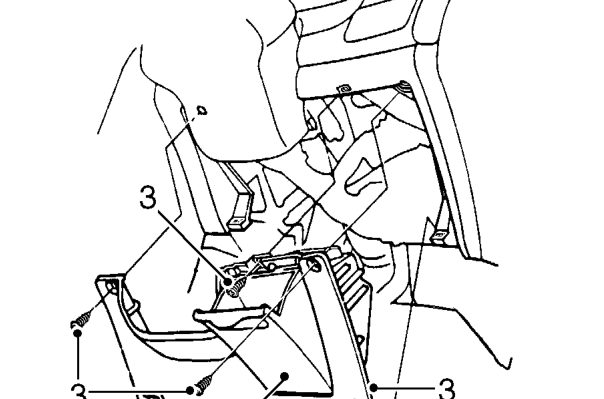
- Remove driver’s pocket from fascia lower cover
- Remove 3 screws and remove fascia lower cover.
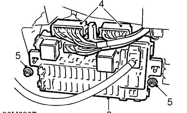
- Release 2 multiplugs from top of fusebox.
- Remove 2 nuts securing fusebox to its mounting bracket.
- Release fusebox from studs.
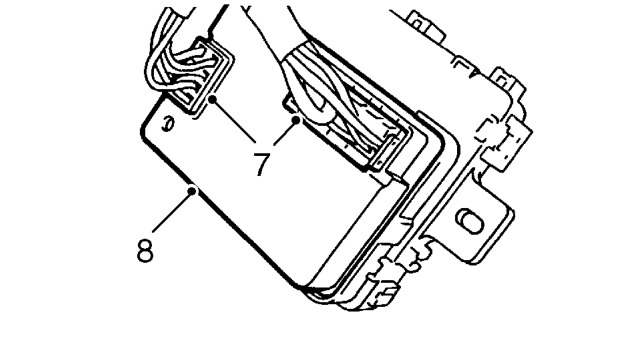
- Disconnect 2 multiplugs from integrated control unit.
- Release integrated control unit from rear of fusebox.
- Remove integrated control unit.
Refit
- Fit integrated control unit to fusebox and secure in position. Connect multiplugs.
- Position fusebox to its studs. Fit and tighten securing nuts.
- Connect multiplugs to the top of the fusebox.
- Fit fascia lower cover and secure with the screws.
- Fit driver’s pocket to the fascia lower cover.
- Connect both battery terminals, earth lead last.
Parts & tools for this job For 1995 Rover 400
- TOOLDigital multimeterSearch: automotive digital multimeter
- PARTAssorted fuse kitSearch: car fuse assortment kit
- TOOLWire crimper and connector kitSearch: wire crimper connector kit
Links open Amazon search results in a new tab. As an Amazon Associate I earn from qualifying purchases.