
Starter switch
- Make
- Rover
- Model
- 400 Workshop Manual
- Year
- 1995–2000
- Section
- Repairs › Starter switch
ElectricalStarter switch · page 1 of 2
Refit
- Clean components and ensure mating faces are free from burrs.
- Apply Molybdenum Disulphide grease to solenoid link and lever, overrun clutch gears and bearings.
- Fit solenoid sealing ring to clutch housing.
- Fit solenoid and secure with screws.
- Fit rubber blanking plug.
- Fit overrun clutch.
- Fit clutch housing and solenoid assembly.
- Fit screws to secure clutch housing.
- Fit armature and housing, fit harness bracket tighten bolts to 9 Nm.
- Connect starter lead to solenoid, tighten nut to 9 Nm.
- Fit rubber cover over terminal.
- Remove starter motor from vice.
- Fit starter motor. See this section.
STARTER SWITCH
Service repair no - 86.65.03
Remove
WARNING: SRS procedures must be followed and all precautions observed. See RESTRAINT SYSTEMS, Precautions.
- Disconnect both battery leads, earth lead first.
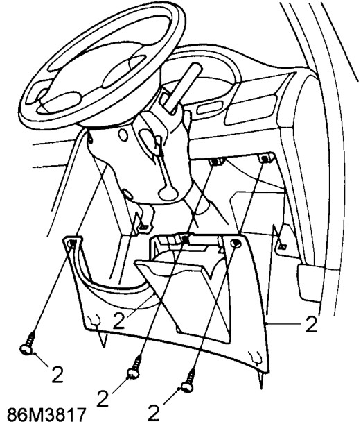
- Remove driver’s pocket, 3 retaining screws and remove lower cover.
Parts & tools for this job For 1995 Rover 400
- TOOLOBD2 scannerSearch: OBD2 scanner
- TOOLDigital multimeterSearch: automotive digital multimeter
- TOOLBack-probe test leadsSearch: back probe test leads
Links open Amazon search results in a new tab. As an Amazon Associate I earn from qualifying purchases.