
Starter switch (page 2 of 2)
- Make
- Rover
- Model
- 400 Workshop Manual
- Year
- 1995–2000
- Section
- Repairs
ElectricalStarter switch · page 2 of 2
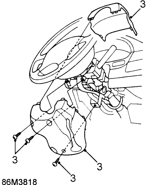
- Remove 3 screws, remove column lower and upper covers.
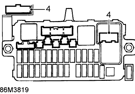
- Disconnect 2 ignition switch multiplugs from fusebox.
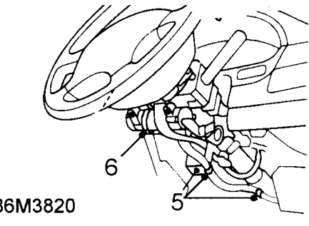
- Release starter switch lead retaining studs from column brackets.
- Remove cable tie securing leads to steering column lock.
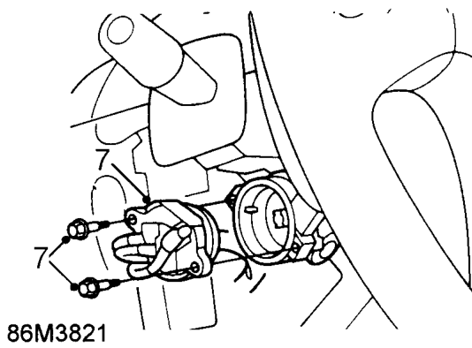
- Remove 2 screws securing starter switch to lock and remove switch.
Refit
- Fit starter switch. Fit and tighten switch retaining screws.
- Fit switch lead studs to column brackets. Fit cable tie to secure lead.
- Connect ignition switch multiplugs.
- Fit column upper and lower covers.
- Fit lower cover and driver’s pocket.
- Connect battery positive and then negative leads.
Parts & tools for this job For 1995 Rover 400
- TOOLOBD2 scannerSearch: OBD2 scanner
- TOOLDigital multimeterSearch: automotive digital multimeter
- TOOLBack-probe test leadsSearch: back probe test leads
Links open Amazon search results in a new tab. As an Amazon Associate I earn from qualifying purchases.