
86M 2031
- Make
- Rover
- Model
- 600 Rover 600 Repair Manual - Volumes 1 and 2 - 2nd Edition
- Section
- Repairs › 86M 2031
Electrical86M 2031
- Check if the pointer and the red mark are aligned. If necessary, adjust ignition timing to the following specifications:
Ignition Timing: 15 ± 2° BTDC (RED)
at 770 ± 50 rpm with gear lever in neutral position and
electrical systems turned – off
Note: The illustration shows A/T.
C
18 Nm
86M 2031
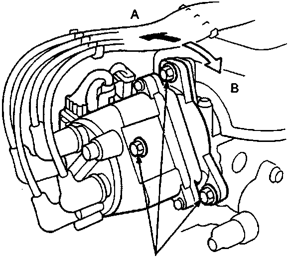
- A To advance
- B To retard
- C Mounting bolts
- To adjust the ignition timing, loosen the distributor mounting bolts, and turn the distributor housing anti – clockwise to advance the timing, or clockwise to retard the timing.
- Tighten the mounting bolts and recheck timing.
- Remove the jumper wire from the service check connector (2 – P) and reinstall the rubber plug into the inspection window.
Idle Speed Inspection
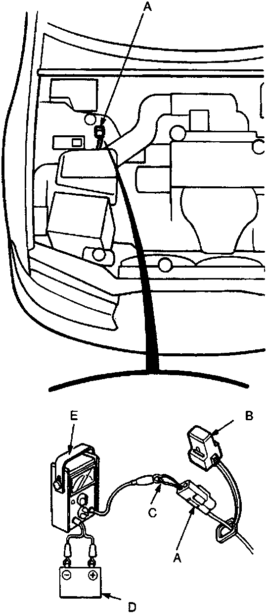
- Start the engine and allow it to warm up (radiator fan comes on).
86M 2032
- A Test tachometer connector (2 – P)
- B Cap
- C Clip
- D Battery
- E Tachometer
Parts & tools for this job For Rover 600
- TOOLDigital multimeterSearch: automotive digital multimeter
- PARTAssorted fuse kitSearch: car fuse assortment kit
- TOOLWire crimper and connector kitSearch: wire crimper connector kit
Links open Amazon search results in a new tab. As an Amazon Associate I earn from qualifying purchases.