
Headlight Washer Switch Test
- Make
- Rover
- Model
- 600 Rover 600 Repair Manual - Volumes 1 and 2 - 2nd Edition
- Section
- Repairs › Headlight Washer Switch Test
ElectricalHeadlight Washer Switch Test
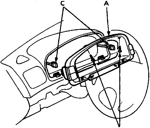
86M2323
- A Instrument panel
- B Screws
- C Connectors
- Remove the two screws and the instrument panel.
- Disconnect each connector from the instrument panel.
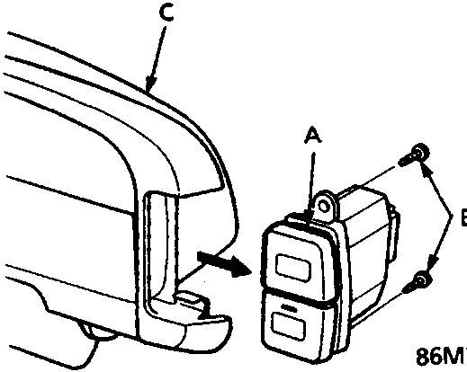
86M2324
- A Headlight washer switch
- B screws
- C Instrument panel
- Remove the two screws and the headlight washer switch.
Headlight Washer Switch Test
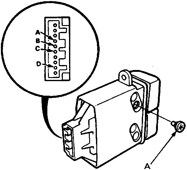
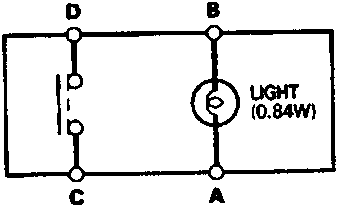
86M2325
- A Bulb (0.85W)
- Remove the headlight washer switch from the instrument panel.
- Check for continuity between the terminals in each switch position according to the table.
| Terminal Position |
A | B | C | D | |
|---|---|---|---|---|---|
| OFF | ● | ● | ● | ||
| ON | ● | ● | ● | ● | ● |
Parts & tools for this job For Rover 600
- TOOLOBD2 scannerSearch: OBD2 scanner
- TOOLDigital multimeterSearch: automotive digital multimeter
- TOOLBack-probe test leadsSearch: back probe test leads
Links open Amazon search results in a new tab. As an Amazon Associate I earn from qualifying purchases.