
Component Location Index
- Make
- Rover
- Model
- 600 Rover 600 Repair Manual - Volumes 1 and 2 - 2nd Edition
- Section
- Repairs › Component Location Index
ElectricalComponent Location Index · page 1 of 2
Component Location Index
CAUTION:
- All SRS electrical wiring harnesses are covered with yellow outer insulation.
- Replace the entire affected SRS harness assembly if it has an open circuit or damaged wiring.
Before disconnecting the SRS wiring harness, turn the ignition switch off, disconnect the negative and positive battery cables, and wait at least three minutes. see SUPPLEMENTARY RESTRAINT SYSTEM
Note: LHD type is shown, RHD type is similar.
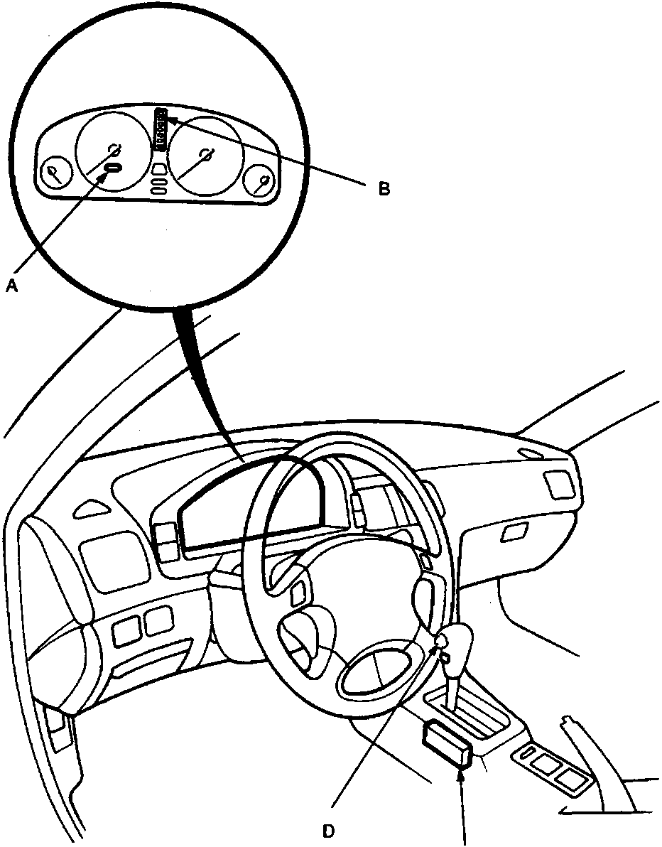
- S indicator
- A/T gear position indicator
- A/T gear position switch
- S switch
Parts & tools for this job For Rover 600
- TOOLDigital multimeterSearch: automotive digital multimeter
- PARTAssorted fuse kitSearch: car fuse assortment kit
- TOOLWire crimper and connector kitSearch: wire crimper connector kit
Links open Amazon search results in a new tab. As an Amazon Associate I earn from qualifying purchases.