
Brake Fluid Level Switch Test
- Make
- Rover
- Model
- 600 Rover 600 Repair Manual - Volumes 1 and 2 - 2nd Edition
- Section
- Repairs › Brake Fluid Level Switch Test
ElectricalBrake Fluid Level Switch Test
Brake Fluid Level Switch Test
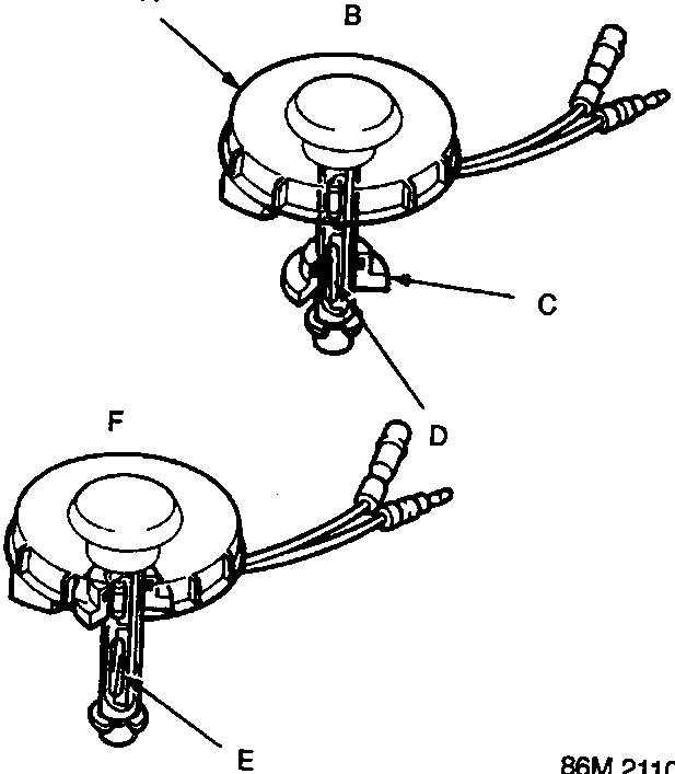
- A Reservoir cap
- B Down position
- C Float (built-in magnet)
- D Switch contacts closed when float drops
- E Switch contacts open when fluid level correct
- F Up position
- Remove the reservoir cap. Check that the float moves up and down freely; if it doesn't, replace the reservoir cap assembly.
- Check for continuity between the terminals with the float up and down.
There should be continuity with the float down and no continuity with the float up. Replace the reservoir cap assembly, if necessary.
Parts & tools for this job For Rover 600
- TOOLBrake bleeder kitSearch: one man brake bleeder kit
- FLUIDBrake fluidSearch: brake fluid
- TOOLBrake line flaring toolSearch: brake line flaring tool
Links open Amazon search results in a new tab. As an Amazon Associate I earn from qualifying purchases.