
Remove
- Make
- Rover
- Model
- 600 Rover 600 Repair Manual - Volumes 1 and 2 - 2nd Edition
- Section
- Repairs › Remove
ElectricalRemove
Remove
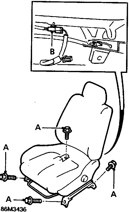
A Seat retaining bolts
B Seat belt harness connector
- Remove 4 bolts and release driver’s seat from its fitted position.
- Tilt seat forward and disconnect seat belt harness connector.
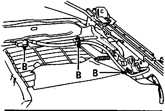
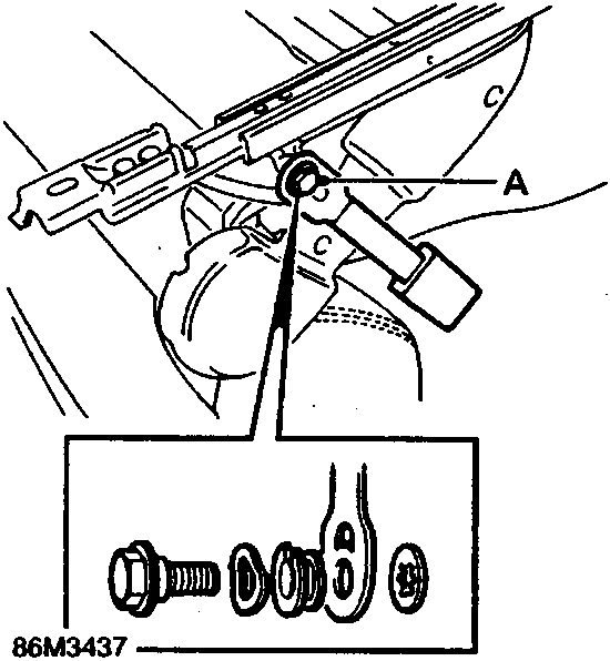
A Anchor bolt – seat belt buckle
B Clips – harness retainers
- Remove anchor bolt securing seat belt buckle to seat frame.
- Remove seat belt buckle and warning light switch assembly.
Refit
- Refit is reversal of removal procedure.
- Ensure the washers are assembled on the anchor bolt as shown.
- Apply thread locking fluid to anchor bolt.
Parts & tools for this job For Rover 600
- TOOLDigital multimeterSearch: automotive digital multimeter
- PARTAssorted fuse kitSearch: car fuse assortment kit
- TOOLWire crimper and connector kitSearch: wire crimper connector kit
Links open Amazon search results in a new tab. As an Amazon Associate I earn from qualifying purchases.