
Installation
- Make
- Rover
- Model
- 600 Rover 600 Repair Manual - Volumes 1 and 2 - 2nd Edition
- Section
- Repairs › Installation
ElectricalInstallation
86M 1994
- Centre – punch each of the two shear bolts and drill their heads off with a 5 mm (3/16 in) drill bit.
CAUTION: Do not damage the switch body when removing the shear bolts.
- Remove the shear bolts from the switch body.
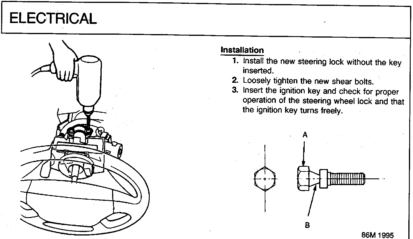
Installation
- Install the new steering lock without the key inserted.
- Loosely tighten the new shear bolts.
- Insert the ignition key and check for proper operation of the steering wheel lock and that the ignition key turns freely.
86M 1995
- Tighten the shear bolts until the hex heads twist off.
| A | Shear bolt |
| B | Twist off position |
Parts & tools for this job For Rover 600
- TOOLDigital multimeterSearch: automotive digital multimeter
- PARTAssorted fuse kitSearch: car fuse assortment kit
- TOOLWire crimper and connector kitSearch: wire crimper connector kit
Links open Amazon search results in a new tab. As an Amazon Associate I earn from qualifying purchases.