
Alternator Overhaul
- Make
- Rover
- Model
- 600 Rover 600 Repair Manual - Volumes 1 and 2 - 2nd Edition
- Section
- Repairs › Alternator Overhaul
ElectricalAlternator Overhaul · page 1 of 2
● When installing the B terminal wire, make sure that the crimped side of the ring terminal is facing out.
Alternator Overhaul
Note: It is only necessary to separate the pulley, drive – end housing, and rotor when the front bearing needs replacement.
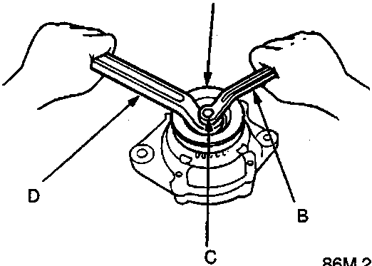
- A Pulley
- B 10mm box spanner
- C Pulley locknut
- D 22mm box spanner
Loosen the puller locknut with 10 mm and 22 mm box wrenches to remove the pulley from the rotor. If necessary, use an impact wrench.
Parts & tools for this job For Rover 600
- TOOLBattery testerSearch: car battery tester
- TOOLDigital multimeterSearch: automotive digital multimeter
- TOOLBattery terminal cleanerSearch: battery terminal cleaner
Links open Amazon search results in a new tab. As an Amazon Associate I earn from qualifying purchases.